Manual
Login
Our 3D CAD supplier models have been moved to 3Dfindit.com, the new visual search engine for 3D CAD, CAE & BIM models.
You can log in there with your existing account of this site.
The content remains free of charge.

Top Links
Manual
 |
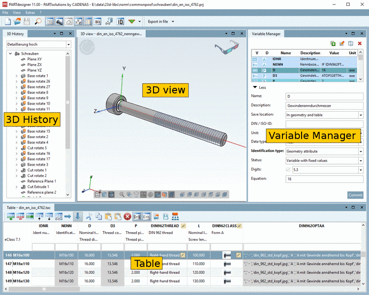
The user interface is subdivided into toolbar, menu bar and docking windows:
At the top you can find the following menus:
File: See Section 7.12, “File management ”.
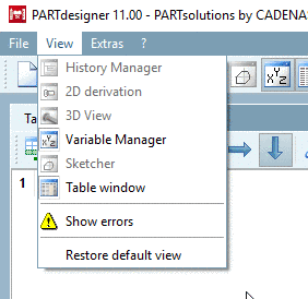
View: See Section 7.13, “ View menu ”.
Extras: See Section 7.14, “ Extras menu ”.
Window: See Section 7.15, “ Window menu ”.
Help: See Section 7.16, “ Help menu (?)”.
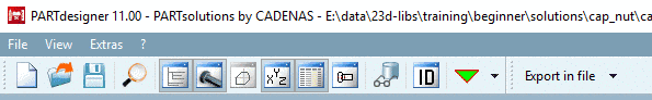
Under the menu bar you can find Standard and Export toolbar with following buttons:
-
New: See Section 7.12.1, “ New ”.
Open: See Section 7.12.3, “ Open ”.
Save: See Section 7.12.4, “ Save or Save as... ”.
 Test part: See
Section 7.17.2, “
Test part
”.
Test part: See
Section 7.17.2, “
Test part
”.-
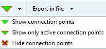
Connection points: List field to show existing connection points or hide them or to hide only active connection points


The main view consists of single docking windows.

You can solve them like in PARTdataManager and move to another monitor.
![[Note]](/community/externals/manuals/%24%7Bb2b:MANUALPATH/images/note.png) |
Note |
|---|---|
|
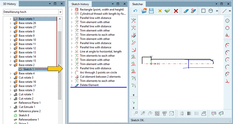
The above figures show the default view, once with 3D History and once with Sketch history and Sketcher.
| |

In the following you will get a short overview on the single docking windows (working areas) with a link to the respective chapter:
-
The docking window 3D History is a central "arena" within PARTdesigner. Via its context menus, the Sketcher (with Sketch history) is opened and the part created.
In the Sketch history all design steps are documented, so that you can retrace later how a part is assembled and possibly modify a step. When calling a new file at first the feature tree only shows the three Base levels XY, ZX, YZ. All other design steps (sketches, rotations, extrusions, etc.) are then listed below.
The button
 or the respective menu item open the docking
window 3D History or bring it into the
foreground.
or the respective menu item open the docking
window 3D History or bring it into the
foreground.
Detailed information on 3D History can be found under Section 7.6, “ 3D History docking window ”.
-
A 3D solid must basically be created via a 2D sketch. This 2D sketch is created in the Sketcher dialog area.
Here, through individual design steps, the sketches are created, which later then create the basis for extrusions and rotations in the 3D History dialog area.
The button Sketcher
 or the respective menu item open the respective
docking window Sketcher and
Sketch history or bring them into the
foreground.
or the respective menu item open the respective
docking window Sketcher and
Sketch history or bring them into the
foreground.
Detailed information on the Sketcher can be found under Section 7.9, “ Sketcher docking window ”.
-
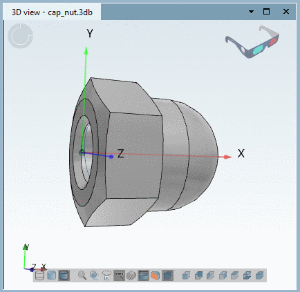
The button 3D window
 or the respective menu item open the docking
window 3D view or bring
it into the foreground.
or the respective menu item open the docking
window 3D view or bring
it into the foreground.
Detailed information on 3D view can be found under Section 7.7, “ 3D view docking window ”.
-
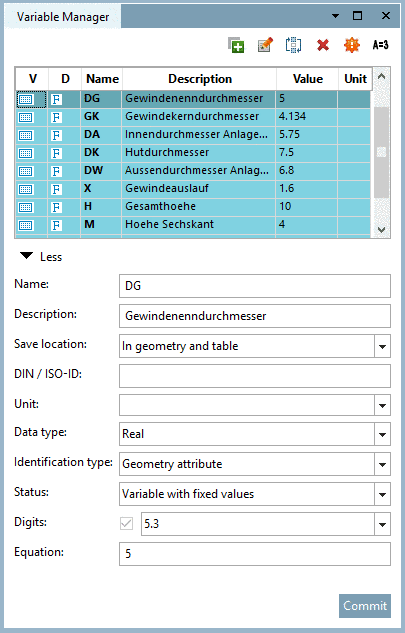
In PARTdesigner, instead of fixed dimensioning values, variables are created, which are filled by concrete values from the characteristic attribute table. This method has the advantage that a new sketch must not be made for each part value (characteristic).
In the docking window Variable Manager, you can create new variables or change already existing variables.
The button Variable Manager
 or the respective menu item open the docking
window Variable Manager
or bring it into the foreground.
or the respective menu item open the docking
window Variable Manager
or bring it into the foreground.
Detailed information on the Variable Manager can be found under Section 7.8, “ Variable Manager docking window ”.
-
The button Table window
 or the respective menu item open the docking
window Table or bring it
into the foreground.
or the respective menu item open the docking
window Table or bring it
into the foreground.
When changing a table line or a value range value, the respective characteristic in the docking window 3D view, Sketcher or 2D derivation is automatically visualized.
When starting PARTdesigner via 3db file, the table is displayed in the lower area of PARTdesigner by default (compare Fig. „PARTdesigner with 3D History, 3D view, Variable Manager and Table “). This view is used as well, if inside PARTdesigner, via File menu -> Open a prj- or 3db file is opened.
When starting PARTdesigner via tab/tac file, the table gets a large area beside Variable Manager. This view is used as well, if inside PARTdesigner, via File menu -> Open, a tab/tac file is opened.
Detailed information on Table can be found under Section 7.11, “ Table docking window ”.
-
The button 2D derivation
 or the respective menu item open the docking
window 2D derivation or
bring it into the foreground.
or the respective menu item open the docking
window 2D derivation or
bring it into the foreground.
In order to display the solid body of the 3D view in 2D mode, please choose a perspective (Front, Back, Right, Left, Top, Bottom) or view under Default views or Combination views.
Also see Section 7.10, “ 2D derivation docking window ”.
Details on 2D view in PARTdataManager can be found under Section 12.2, “ Create 2D derivation ”.