Manual
Login
Our 3D CAD supplier models have been moved to 3Dfindit.com, the new visual search engine for 3D CAD, CAE & BIM models.
You can log in there with your existing account of this site.
The content remains free of charge.

Top Links
Manual
 |
- 3.1.7.6.1. 3D view Toolbar
- 3.1.7.6.2. Determine Level of Detail
- 3.1.7.6.3. Measurement of 3D parts
- 3.1.7.6.4. Measuring grid
- 3.1.7.6.5. Show Dimensionings
- 3.1.7.6.6. Change characteristic via dimension labels
- 3.1.7.6.7. Define section cut...
- 3.1.7.6.8. Part designation (Standard name [NB] / BOM name [LINA])
|
The characteristic chosen in the Table or List is immediately displayed in the 3D window. For visual component testing there are a number of functions available to you: |
|
-
To control the 3D preview use the buttons of the 3D preview toolbar.The most important functions are summarized here.
If you move the cursor over the buttons, the display of a button changes from dimmed to full-color.
Activated buttons (Shaded with edges exemplarily in the next figure) are displayed a little bit darker.
More detailed information about the individual buttons can be found under Section 3.1.7.6.1, “ 3D view Toolbar ”.
-
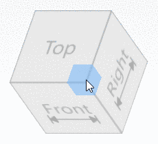
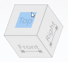
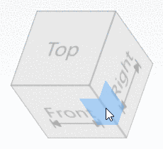
Optionally, you can display an Orientation cube instead of the coordinate system. Use it, in order to simply rotate the 3D view. Click on an edge, corner or face, in order to bring it in the front. Clicking on a face repeatedly will rotate the part around face's vertical.
Faces with arrows have dimensionings in addition (like the icons in the toolbar).
In order for the orientation cube to be displayed, in PARTdataManager in the Extras menu under Settings... -> 3D settings -> tabbed page Elements -> Type of coordinate system (small), select the option Orientation cube, otherwise the Coordinate system will be displayed instead.
-
With the mouse functions left mouse button, right mouse button, both right and left mouse button pressed at the same time you can carry out the following operations:
-
By right-clicking into the 3D window you reach the context menu.
There you have some commands of the 3D toolbar available in parallel, in addition some more commands:
Define sectional plane... (see Section 3.1.7.6.7, “ Define section cut... ”)
Measure... (see Section 3.1.7.6.3, “ Measurement of 3D parts ”)
Measure grid (see Section 3.1.7.6.4, “ Measuring grid ”)
A detailed description of all context menu commands can be found under Kontextmenüs 3D / 2D / Technische Angaben.
More detailed information about the individual buttons of the toolbar can be found under Section 3.1.7.6.1, “ 3D view Toolbar ”.
-
The coordinate system is displayed on the bottom left per default. You can change this under Extras -> Settings.... (on/off, position).
-
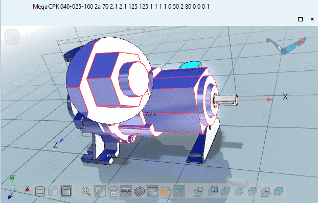
With a pair red-cyan glasses you can see the assembly even more realistically in 3D.
The default display is on the top right. You can change the display under Extras -> Settings.... (on/off, position).