Manual
Login
Our 3D CAD supplier models have been moved to 3Dfindit.com, the new visual search engine for 3D CAD, CAE & BIM models.
You can log in there with your existing account of this site.
The content remains free of charge.

Top Links
Manual
 |
In the following a simple characteristic attribute table shall be created.[77]
-
In PARTproject, create a new project. A small example on this can be found under Section 5.5, “Create project - Small example from A to Z ”.
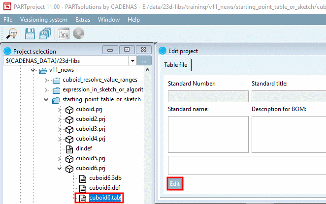
In the project to be edited, select the *.tab or *.tac file.
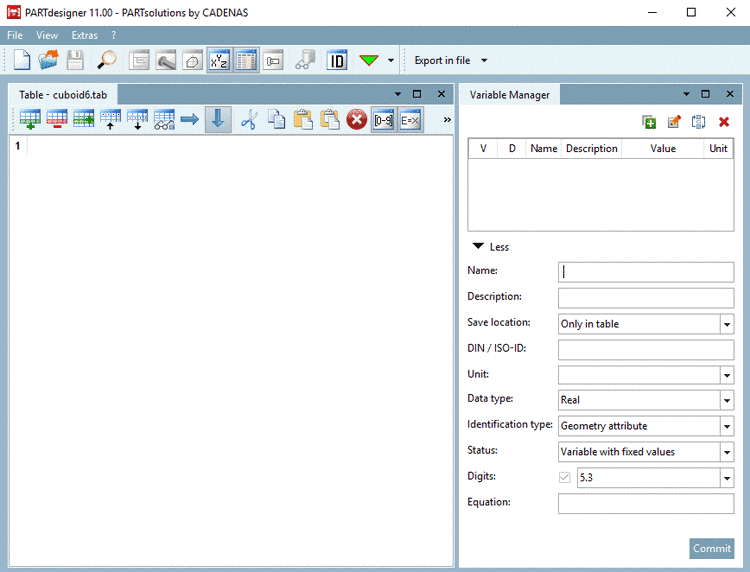
--> PARTdesigner is opened in the table view.
In the table view, the docking window Variable Manager is opened together with the docking window Table by default.
![[Note]](/community/externals/manuals/%24%7Bb2b:MANUALPATH/images/note.png)
Note -
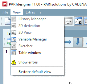
If needed, show/hide single docking windows via respective buttons of the Default toolbar or menu items in the View menu.
Move single docking windows or adjust them in size. A detailed description on the placing method can be found under Section 3.1.5.4, “Placing method for dockings ” in PARTsolutions / PARTcommunity4Enterprise - User manual.
-
-
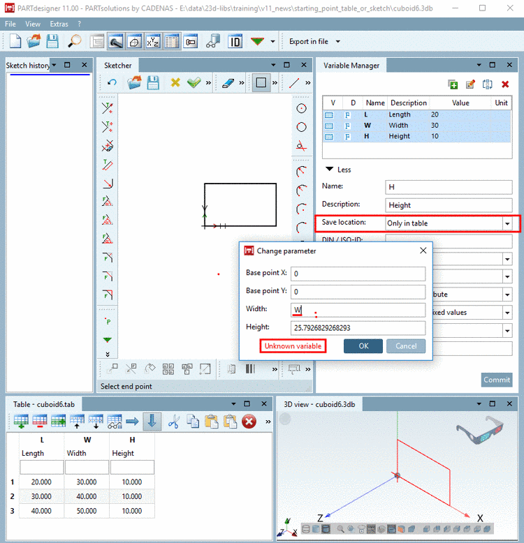
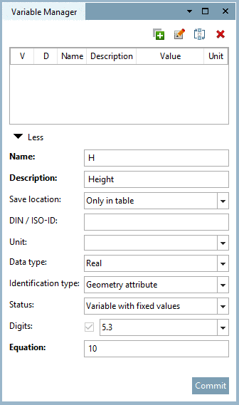
In the Variable Manager, create the variables L (Length), W (Width) and H (Height) for a cuboid. Details on the Variable Manager can be found under Section 7.8, “ Variable Manager docking window ”.
-
Under Save location the option Only in table is already selected since PARTdesigner has been opened via tab file.
Using this option all input fields are active. Details on the individual parameters can be found under Section 7.8.9, “ Variable Manager - The individual parameters”.
For starters orient by the following figure.
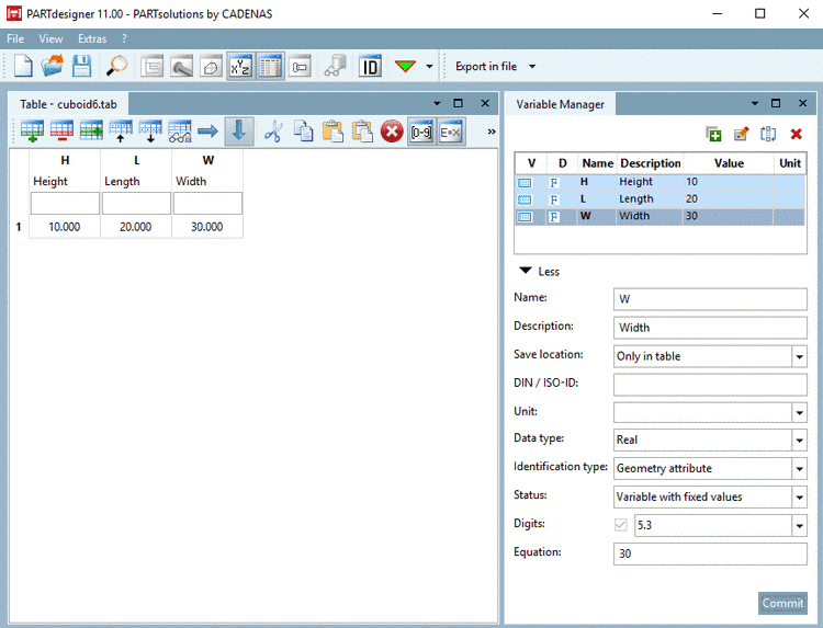
--> Once after creation of a variable in the Variable Manager, it is also displayed in the table.
-
-
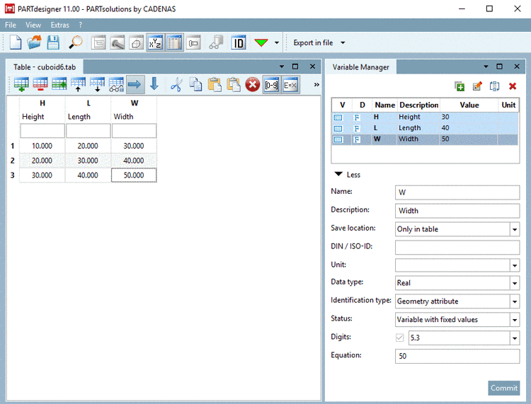
Add other characteristics by clicking Add row
 .
. -
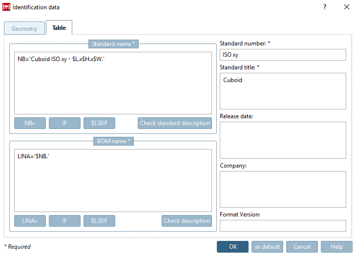
-> The dialog box Identification data is opened with tabbed page Table. Fill out the mandatory fields Standard name, Description for BOM, Standard number and Standard title. Details on this can be found under Section 7.12.7, “ Identification data ”.
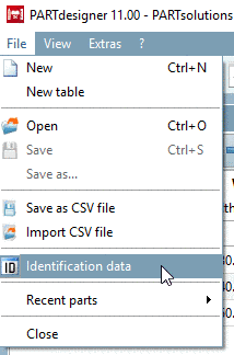
The dialog box can be opened via File menu -> Identification data or via
 anytime.


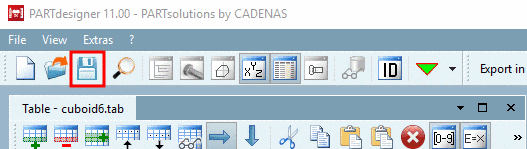
After finishing the table, in the next step the 3D model is created.
Therefor, open the 3db file from PARTproject. The variables are automatically overtaken from the related (same-named) tab/tac file.
-
For all variables to be used in the sketch, under Save location, select the option In geometry and table. Details on this can be found underSection 7.8.10, “ Save location: Only in geometry | Only in table | In geometry and table ”.[78]
Otherwise the error message Unknown variable is displayed.
Create the 3D model based on the created variables. A small example on this can be found under Section 7.4, “Create 3D model: Small example from A to Z ”.