Login
Our 3D CAD supplier models have been moved to 3Dfindit.com, the new visual search engine for 3D CAD, CAE & BIM models.
You can log in there with your existing account of this site.
The content remains free of charge.

Top Links
Categories


Search FAQs
Most Recent FAQs
-
0 comments, 0 likes, 3,533 views100% helpful.
-
0 comments, 0 likes, 4,755 views100% helpful.
-
0 comments, 0 likes, 10,632 views
Most Viewed FAQs
-
0 comments, 0 likes, 129,302 views0% helpful.
-
0 comments, 0 likes, 24,696 views
-
0 comments, 0 likes, 21,387 views18% helpful.
FAQs
-
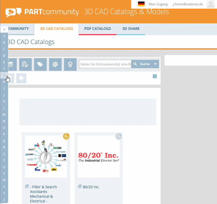
Under 3D CAD CATALOGS you have the possibility to chooses CAD formats and to define the handing over mode into the CAD system. 1. ...Under 3D CAD CATALOGS you have the possibility to chooses CAD formats and to define the handing over mode into the CAD system.
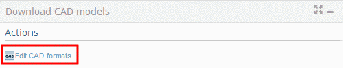
1. Make sure that you are in the dialog area 3D CAD CATALOGS.2. On the right side under Actions, click on Edit CAD formats

-> The following dialog are shows up:
- Generation options (Level of Detail)
- Selected Formats (Add CAD formats)
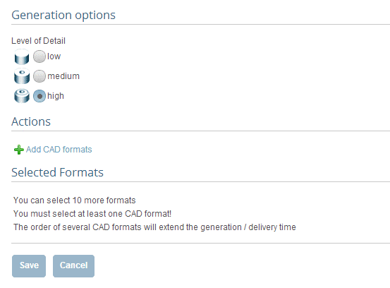 3. Click on Add CAD formats.
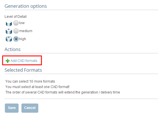 -> The settings area for Generation type and Format selection opens.
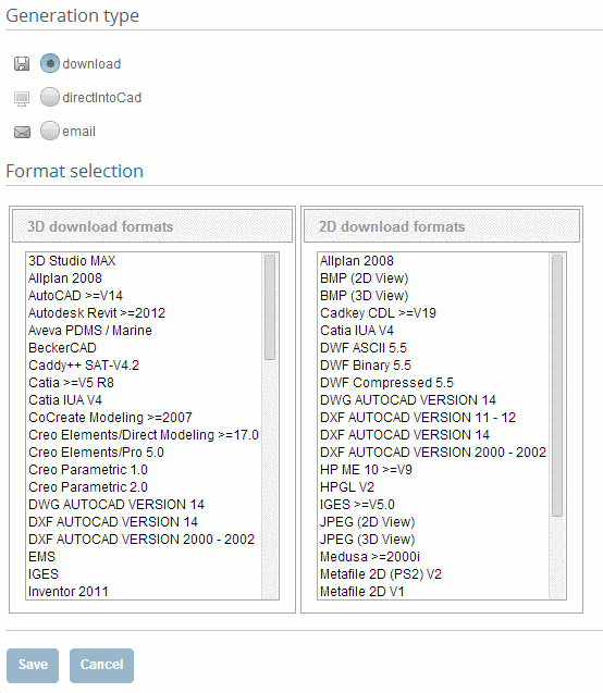 4. First determine the desired generation type. Click into the desired option field.
-> In the dialog area Format selection select a format or several formats.5. Click on Save.
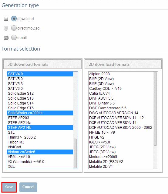
-> The view changes back to the dialog area Generation options / Selected formats.
In the dialog area Selected Formats you can see your current selection.
In addition to that under Actions you can define the Level of Detail.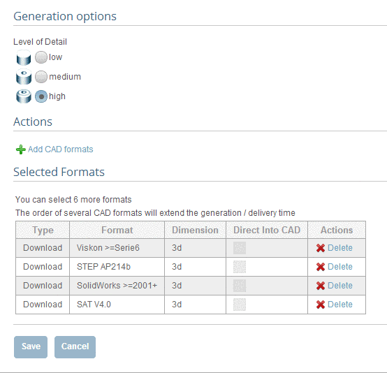 6. Confirm your entries with Save.
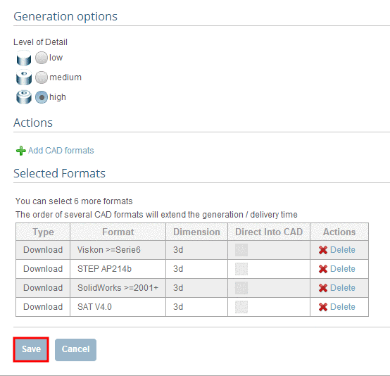 Permalink | 0 comments, 0 likes, 9,255 viewsWas this answer helpful?
 -
Follow the steps listed below to generate a PDF datasheet: Make sure that you are in the dialog area 3D CAD CATALOGS and select t...
Follow the steps listed below to generate a PDF datasheet:
- Make sure that you are in the dialog area 3D CAD CATALOGS and select the desired catalog.
- At directory level
 select product groups as long as a concrete assembly
 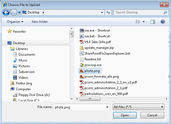 or concrete single part
  has been specified.
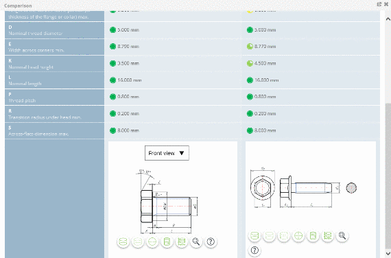
-> As soon as a concrete row has been determined, a 3D view and dimensional drawings are loaded under CAD model preview.
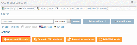
- Under Actions, click on Generate PDF datasheet.
- The information dialog Generation CAD models opens.
Note
If the CAD model shall be generated in several formats under Format selection there is the possibility to choose the format PDF Datasheet additionally. By holding down the CTRL key, you can make multiple selections.

- Under Actions, click on Generate CAD model.
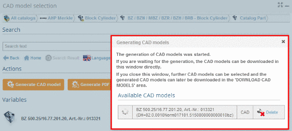
- The information dialog Generating CAD models opens.
-> The generation was started.
The following symbols show the generation status: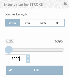 Active generation
 Generation erroneous
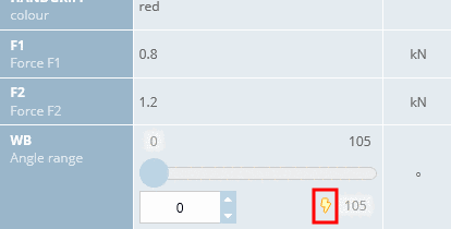 Generation successfull. Part ready for download.
Note
The pregenerated 3D PDF corresponds to a sample part (created for a mid-row with standard setting) and may differ from your selected part.
Permalink | 0 comments, 0 likes, 9,203 viewsWas this answer helpful? -
Follow the steps listed below to carry out the geometric similarity search: Make sure that you are in the dialog area 3D CAD ...
Follow the steps listed below to carry out the geometric similarity search:
-
Make sure that you are in the dialog area 3D CAD CATALOGS and search for the required part.
-
At directory level
 select product groups as long as a concrete assembly
  or concrete single part
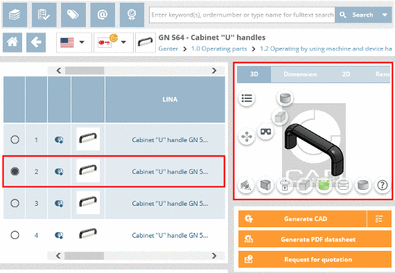
  has been specified. Select the desired part by clicking into the option button before the desired row.
-
Click on Geometrical Search.

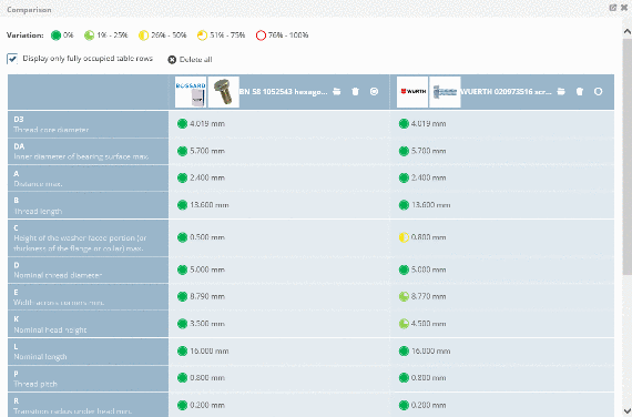
-> The similar parts found are listed in the dialog area Results.
Permalink | 0 comments, 0 likes, 9,061 viewsWas this answer helpful? -
-
Follow the steps listed below to generate your desired part: Make sure that your are in the dialog area 3D CAD CATALOGS&nbs...
Follow the steps listed below to generate your desired part:
- Make sure that your are in the dialog area 3D CAD CATALOGS and select the desired catalog.
-
At directory level
 select product groups as long as a concrete assembly
  or concrete single part
  has been specified.
-> A soon as a concrete row has been determined, a 3D view and dimensional drawings are loaded under CAD model preview.
-
In the dialog area Download CAD models under Actions define the generation type and the desired CAD formats by clickingEdit CAD formats.
-
The information dialog Generating CAD models opens.
Permalink | 0 comments, 0 likes, 8,799 views0% users marked this FAQ as helpful.|2 votesWas this answer helpful? -
1.) Go to https://b2b.partcommunity.com/community/partcloud/index#!upload-parts Interesting: Choosing the right license
-
With the so-called HotSpot function, additional diverse information can now be linked with a preview of the uploaded component. Those 3...
With the so-called HotSpot function, additional diverse information can now be linked with a preview of the uploaded component. Those 3D CAD models become an interactive encyclopedia for engineers and members of the PARTcloud.net sharing community.
Besides videos and animated graphics, members of the community can also provide descriptions of the 3D CAD model and explain their own designs. The advantage is also shown with the sharing or embedding of the 3D CAD model in other websites: The information remains unchanged and engineers can obtain a first impression at once.
How to do it? It is very simple, just follow these guide lines:
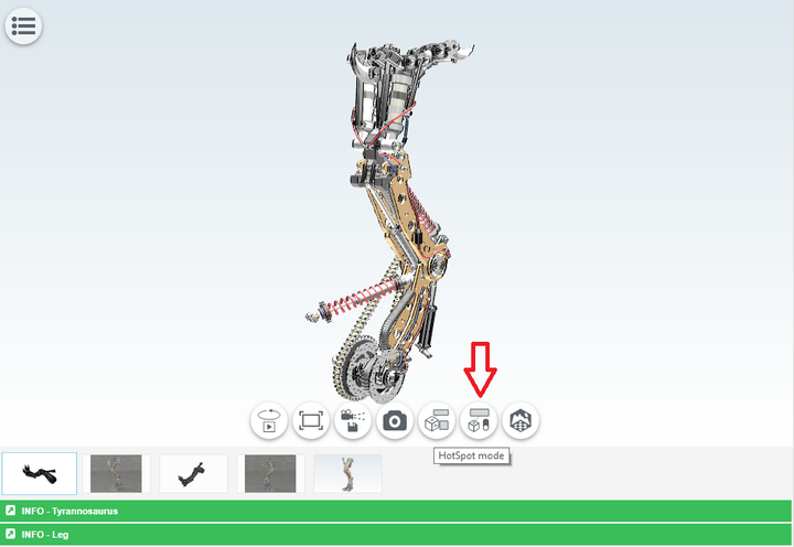
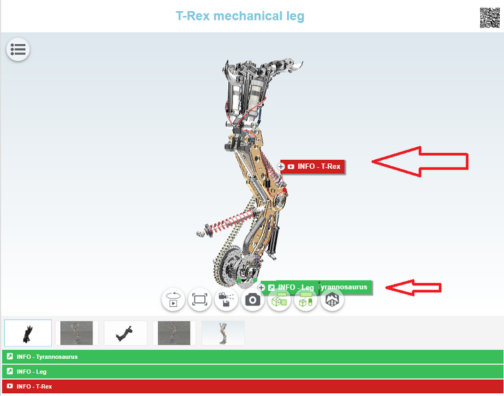
1. Once your 3D model is uploaded on PARTcloud.net, a HotSpot can be added. Click on the icon "HotSpot Mode".
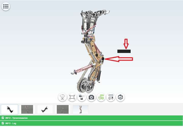
2. Choose the HotSpot location on your 3D model and click to confirm it. The "black box" is a place where the title will be shown.
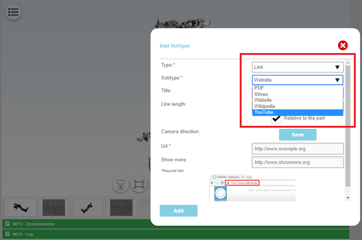
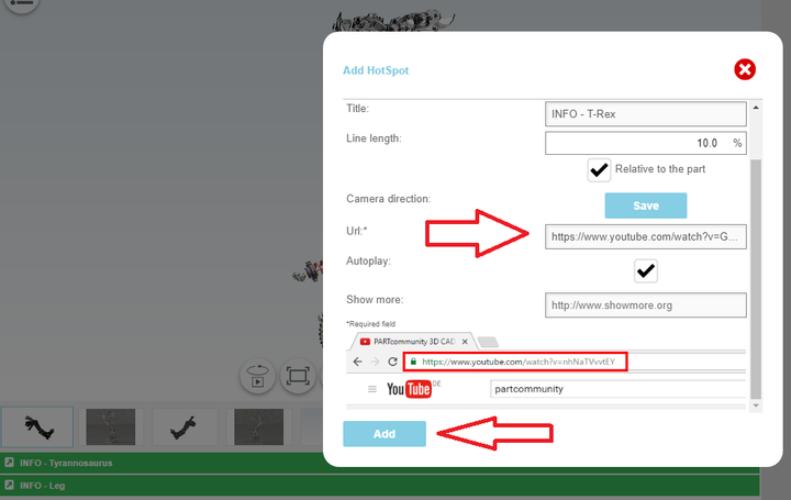
3. Choose among options depending on what you would like to add. A new window appears where the information can be selected that is to be filed. Users then have a choice between texts, links, images, videos and manufacturer catalogs. The latter shows engineers, for example, which standard parts were used in the design. In this case, we will use "Link" and then "YouTube" in order to show a video clip. If you want to add an article, you can choose "Wikipedia" - it is all up to you.
4. Add the title of info you would like to provide.
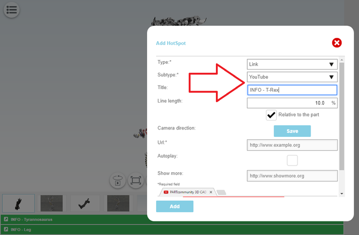
5. Find what you are looking for (in this case, a video clip from YouTube) and copy-paste the link. Click on "Add".
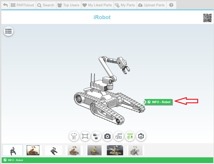
6. The HotSpot should appear beside your 3D model. You can add as many HotSpots as you like. We added one more in this case (on bottom) to make it educational and more interesting like that.
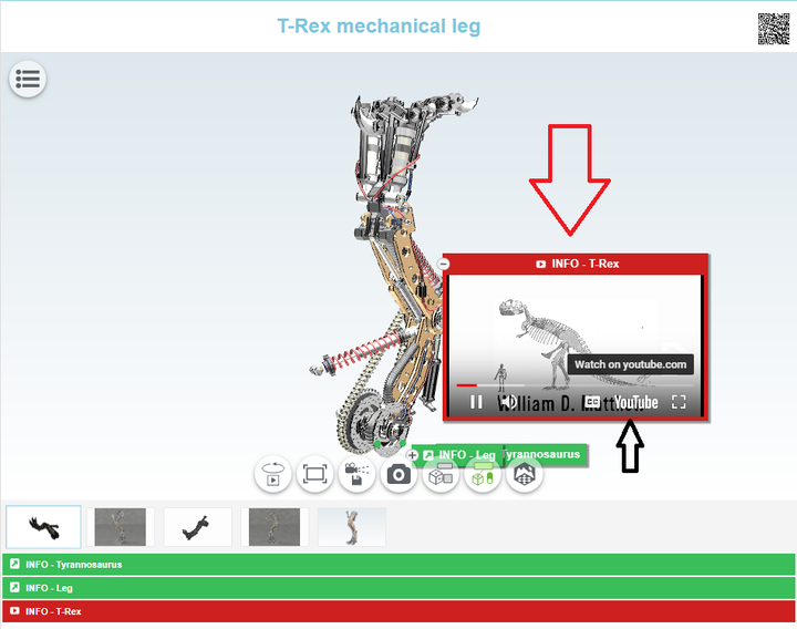
7. Click on it and you can watch that specific YouTube video clip. You can also click on YouTube to take you directly there (black arrow). Once again, you can add any other HotSpot depending on what you would like to show: Wikipedia article, PDF catalog, Vimeo, photo, website, etc.
https://www.youtube.com/watch?v=gY6o2_8Fqu8
Permalink | 0 comments, 3 likes, 8,599 views100% users marked this FAQ as helpful.|9 votesWas this answer helpful? -
Overview to the quality characteristics Gold Quality Seal Available in many languages Levels of detail included (LOD...
-
Log in with your access data and click on the button My Profile. On the right side, under Profile Options, cli...
-
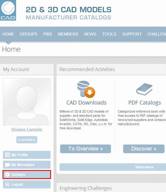
Log in with your access data and click on the button My Profile.
-
On the right side, under Profile Options, click on Edit My Profile.
Permalink | 0 comments, 0 likes, 8,483 viewsWas this answer helpful? -
-
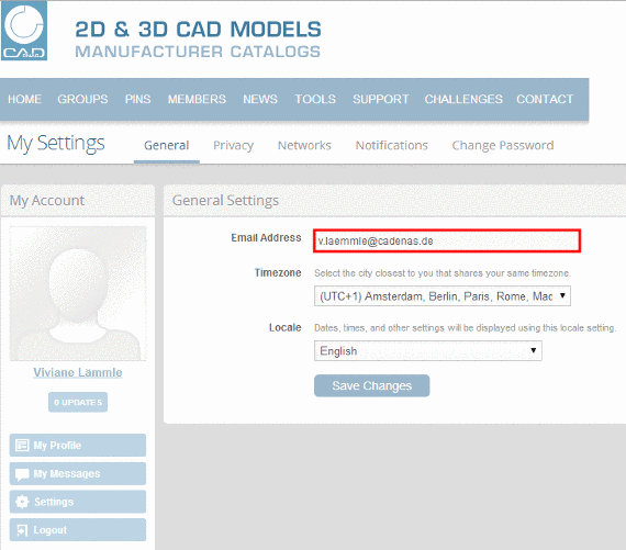
1. Log in with your access data and click on the button Settings. 2. Click inside the field Email Address and enter your new e-m...
1. Log in with your access data and click on the button Settings.
2. Click inside the field Email Address and enter your new e-mail address.
3. Confirm the data by clicking the button Save Changes.
-> The confirmation Settings were successfully saved is displayed.
Permalink | 2 comments, 0 likes, 8,454 viewsWas this answer helpful? -
Follow the steps listed below to send a request for quotation: Make sure that you are in the dialog are 3D CAD CATALOGS and sele...
Follow the steps listed below to send a request for quotation:
- Make sure that you are in the dialog are 3D CAD CATALOGS and select the desired catalog.
- At directory level select product groups as long as a concrete assembly or concrete single part
 has been specified.
-> As soon as a concrete row has been determined, a 3D view and dimensional drawings are loaded under CAD model preview. - Under Actions click on Request for quotation.

-> The dialog for inputting your quotation request opens.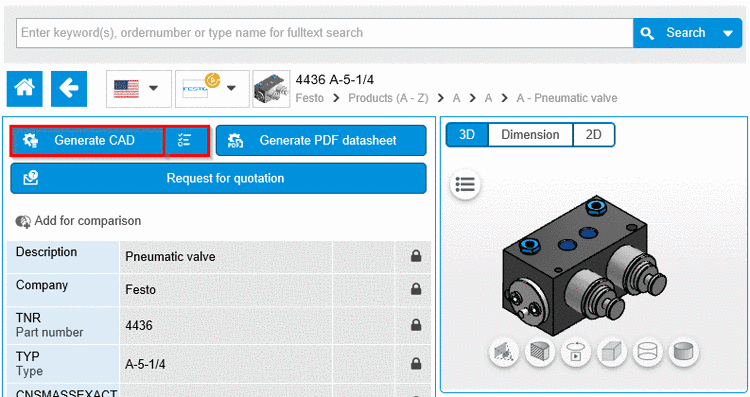
Fill in the input fields completely and click on Send request, to send the request. 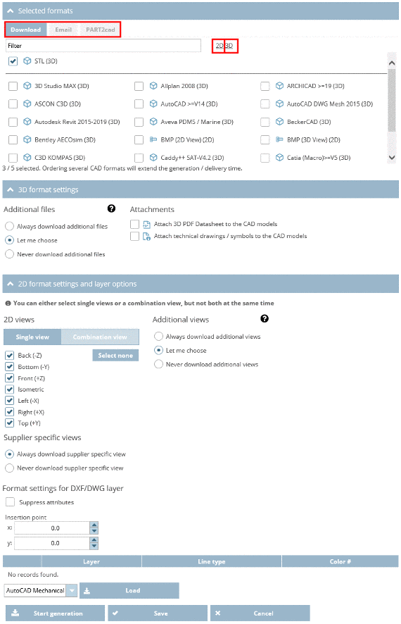
Note
In order to get a preview of your enquiry click on Preview request.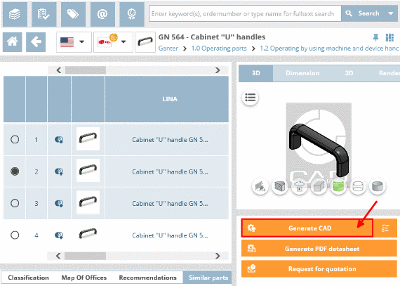
-> A dialog box with a preview of the request opens.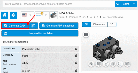
- As soon as the e-mail was sent, you will receive the confirmation Email has been sent successfully.

Permalink | 0 comments, 0 likes, 8,256 viewsWas this answer helpful? -
Follow the steps listed below to integrate the chosen CAD model into your CAD system directly: Make sure that you are in the d...
Follow the steps listed below to integrate the chosen CAD model into your CAD system directly:
-
Make sure that you are in the dialog area 3D CAD CATALOGS and navigate to the required part.
-
In the dialog area Download CAD models under Edit CAD formats -> Add CAD formats, select the transfer mode directIntoCad by clicking into the option field. Then define the CAD system and confirm your entries by clicking on Save.
-> The view returns to the dialog area Generation options / Selected formats. Confirm your entries by clicking on Save.
-
Under Actions, click on Generate CAD model.
-> The information dialog Generating CAD models opens.
Note
All formats activated under Download CAD models(dialog area 3D CAD CATALOGS) -> Edit CAD formats -> Selected Formats are generated and listed here now.
As long as the generation is running, is shown.
-
As soon as the generation has completed, you can submit the CAD models to the CAD system in this window directly by clicking the link Direct integration.
If you close this window, further CAD models can be selected.
Furthermore all generated CAD models are listed under Download CAD models.
-> In the transfer mode Direct integration into CAD system the link text in the column Actions will be the following:
-
By clicking the link Info specific part information is displayed:
-
Click on the link Direct integration or the symbol
 , in order to load parts into the CAD system.
Note
The application component PART2cad is required at the workstation when using direct integration.
Install it during the first run. The necessary installer opens automatically.
The installer itself needs Java.
-> Once Java is installed the PART2cad installation will start. If Java is not installed, there will be no Java logo displayed. In this case click on the link Click here and install Java.
-> Warning messages may show up. Let the component PART2cad install.
During the first run the direct integration PART2cad will be downloaded.
Following runs will open the dialog Transferring model to CAD. No user interaction is necessary.
-
In the drop-down menu select the CAD version where the model is to be transferred. Confirm the selection with Choose.
-> A dialog box "Export ..." is opened to select the destination directory.
-
Select the preferred destination directory. Use ... to browse. Confirm your entries by clicking Ok.
-> The model is transferred to the CAD system.

Note
When the transfer to the CAD system is finished a message will be shown.Please note the following selection dialog for the version name of the CAD system.
-> The part has been imported in the CAD system.
If the CAD system is not started or the wrong version was chosen, an error message will be shown.
Permalink | 0 comments, 0 likes, 8,218 viewsWas this answer helpful? -
-
Use the filter, especially for parts with many rows (characteristics), in order to minimize the number of displayed rows. Follow t...
Use the filter, especially for parts with many rows (characteristics), in order to minimize the number of displayed rows.
Follow the steps listed below to filter for certain variables:
-
Make sure that your are in the dialog area 3D CAD CATALOGS and search for the required part.
-
At directory level
 select product groups as long as a concrete assembly
  or concrete single part
  has been specified and choose an assembly or a single part.
-
For tables with many values (columns) switch into Full screen mode by clicking on the icon
 .
.
-
Click on the filter symbol
 in the column header of the respective variable with which you want to filter.
-
Make your preferred settings. Then click on Apply to confirm your entries.
-> If you want to change your entries click on Reset. If you want to return without changes click on x.
-> Only CAD models are shown which correspond to the filter settings.
-
In order to delete the filter settings, click on Remove all filters.
Permalink | 0 comments, 0 likes, 8,144 views100% users marked this FAQ as helpful.|1 voteWas this answer helpful? -
-
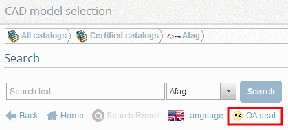
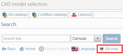
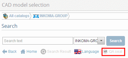
A corresponding icon is shown at catalogs with quality seal. If the catalog hasn't got a quality seal the link is inactive (greyed out). ...
-
https://stephaneginier.com/sculptgl/ SculptGL is a digital sculpting web app, with sources available on github. ...
https://stephaneginier.com/sculptgl/
- SculptGL is a digital sculpting web app, with sources available on github.
- Also available on the chrome web store.
- If you want to download a standalone version, you can download it here (identical as the web version).
- Sketchfab made a fork of the old SculptGL version with a new design : Sculptfab.
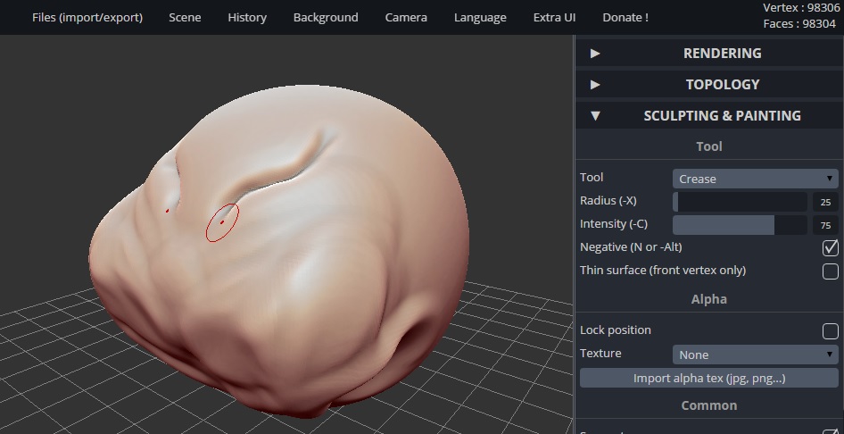
Main features :
- Sculpting tools
- Standard tools : Brush, Inflate, Smooth, Twist, Drag, etc
- PBR Vertex Painting (color, roughness, metalness)
- Alpha texture support for each tools
- Multiresolution sculpting
- Quad-tri Subdivison (catmull-clark/loop)
- Reversion (compute opposite of subdvision if possible)
- Navigating from low/high poly level subdiv will retain sculpting changes
- keep UVs (both reversion and subdivison)
- Voxel remeshing
- Uses SurfaceNets meshing algorithm (produces quad-only mesh)
- Uniform remeshing (quads will have the same size)
- Can also create non-manifold vertex :(
- In case of a non closed mesh, a naive holefilling algorithm is performed first
- Deletes UV
- Dynamic topology
- Triangles only
- Operates in real time
- Local subdivision (create new triangles)
- Local decimation (deletes triangles)
- Deletes UV
- Supports OBJ, PLY, STL import/export
- Reads vertex color
- Optimizes post and pre transform cache (tipsy algorithm)
- Undo/Redo support
Permalink | 0 comments, 0 likes, 8,086 viewsWas this answer helpful? -
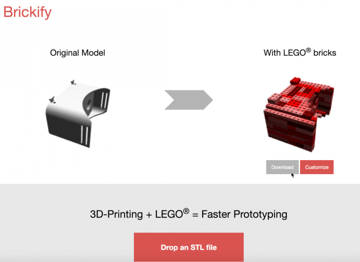
https://brickify.it/ 3D-Printing + LEGO® = Faster Prototyping
https://brickify.it/
3D-Printing + LEGO® = Faster Prototyping
 Permalink | 0 comments, 0 likes, 7,798 views100% users marked this FAQ as helpful.|1 voteWas this answer helpful?
 -
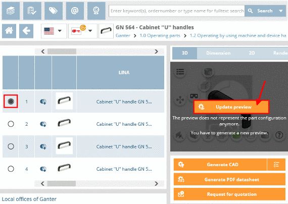
Some parts contain value range fields. In order to completely specify the part, a selection must be made in the value range fields. ...
Some parts contain value range fields. In order to completely specify the part, a selection must be made in the value range fields.
The settings are made in the Variables section.
Follow the steps listed below to set the value ranges:
-
Make sure that you are in the dialog area 3D CAD CATALOGS and search for the required part.
-
At directory level
select product groups as long as a concrete assembly or concrete single part has been specified. Select the desired part by clicking into the option button before the desired row. -
Click on the part description in order to reach the variable view.

-> You will recognize the value range fields based on their yellow background color.
There are different types of value range fields:- List fields
Using the arrow open the value range field and select the desired value.

Then select the desired value.

- Input fields or selection via slider
Enter the desired value manually or set it using the slider in the given area.
Note
Inputs outside of the allowed value range are automatically corrected.
- Value range fields with images
Some catalogs support images for variant selection.
Click on the image in order to set another value.
-> A dialog opens for choosing the characteristic per image.
Select the desired variant by clicking on the image.
-> It is reloaded into the variable view.
If you do not want to take over the changes, click on x.
The part is now completely specified.
Permalink | 0 comments, 0 likes, 7,727 viewsWas this answer helpful? -
-
You can embed an interactive view of your 3D CAD models and assemblies into your website and many CAD manufacturers are already doing it....
You can embed an interactive view of your 3D CAD models and assemblies into your website and many CAD manufacturers are already doing it.
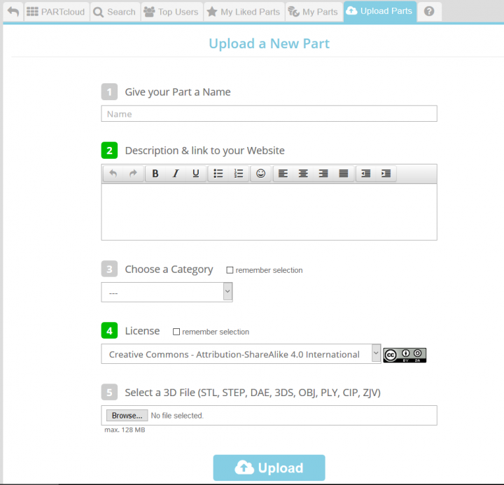
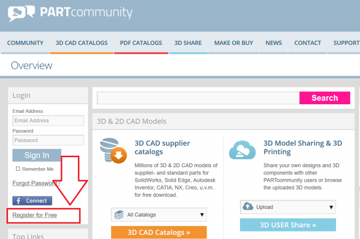
1. Create an account on PARTcloud.net

2. Click on the upload button at the top of the page. You will then be asked to select a file(s) and to fill out some details about the part before uploading it.
3. Once the part of assembly has been uploaded, you will be able to see it in your portfolio.
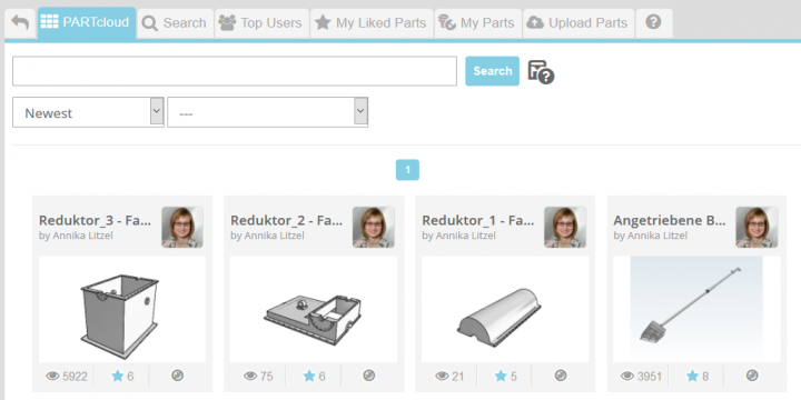
4. If you view the part in your portfolio, you will see a box labelled "Configure your code and use it in your website".
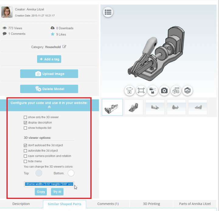
5.There are options available on how your part is shown and which aspects are visible. Underneath those options, an Iframe will be configured, which you can embed into your website. Before copying the code into your website you can test it. Click on the button “Try it” and you will be forwarded to a new site.
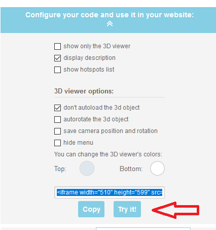
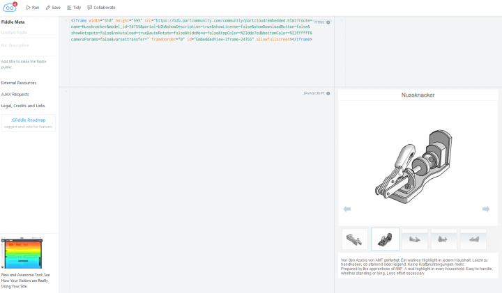
Here you can test and modify your code. The size of the viewer can be adjusted by the width and height figures in the code. Afterwards: Copy this code and paste it into your website.
6. When you preview the webpage, you will now be able to see the interactive window displaying your files.
Permalink | 0 comments, 0 likes, 7,112 views100% users marked this FAQ as helpful.|2 votesWas this answer helpful? -
1. Register on PARTcommunity.com 2. Upload your 3D model on 3D SHARE - PARTcloud.net 3. Choose "Cha...
1. Register on PARTcommunity.com
2. Upload your 3D model on 3D SHARE - PARTcloud.net
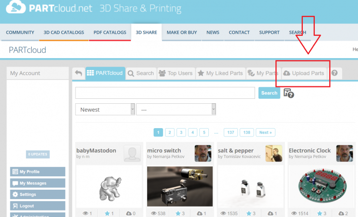
3. Choose "Challenges" category (no need to choose subcategory). First you upload files, then renders (Upload Image).
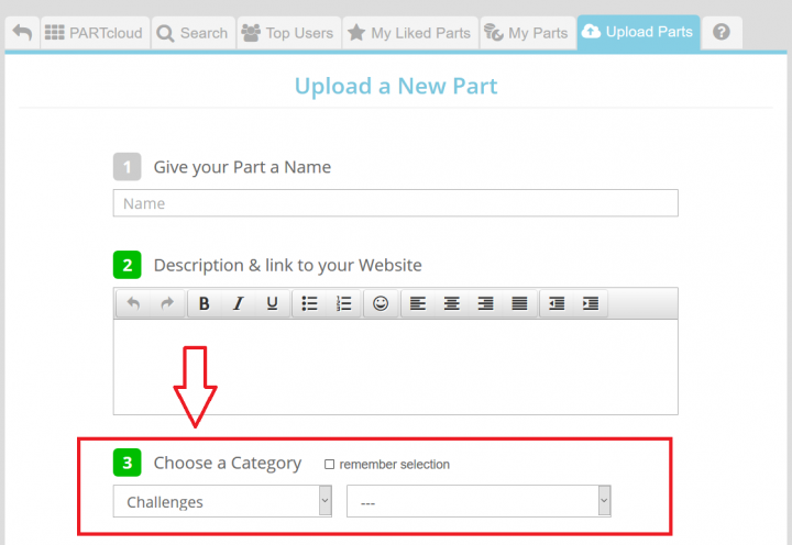
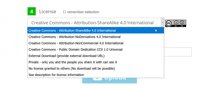
4. Choose the right license depending on your choice.
5. Done. You can upload as many 3D models as you wish for the Weekly Challenge and good luck!
Permalink | 3 comments, 1 like, 6,880 views88% users marked this FAQ as helpful.|8 votesWas this answer helpful? -
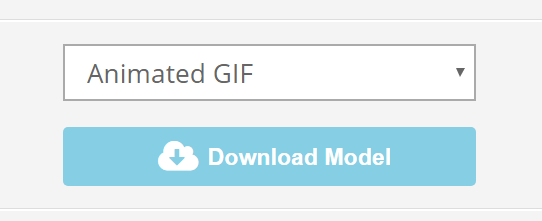
Choose download option ANIMATED GIF
-
http://www.embossify.com/ Convert 2D pictures and drawings into 3D STL (Stereolithography) files suitable for 3D printing or C...
Convert 2D pictures and drawings into 3D STL (Stereolithography) files suitable for 3D printing or CNC routing. Turn JPEGs into lithophanes, reliefs, and other 3D design elements.
Features- Free low resolution ( ~ 108k facets ) renderings.
- $5 per high resolution rendering.
- Converts JPEG data to a STL (Stereolithography) file.
- Creates a perfectly enclosed tessellation of rendered 3D mesh.
Lighter the pixel, deeper facet in the mesh. Invert depth for the opposite.
 Permalink | 0 comments, 0 likes, 6,761 viewsWas this answer helpful?