Login
Our 3D CAD supplier models have been moved to 3Dfindit.com, the new visual search engine for 3D CAD, CAE & BIM models.
You can log in there with your existing account of this site.
The content remains free of charge.

Top Links
Categories


Search FAQs
Most Recent FAQs
-
0 comments, 0 likes, 3,533 views100% helpful.
-
0 comments, 0 likes, 4,753 views100% helpful.
-
0 comments, 0 likes, 10,631 views
Most Viewed FAQs
-
0 comments, 0 likes, 129,301 views0% helpful.
-
0 comments, 0 likes, 24,695 views
-
0 comments, 0 likes, 21,386 views18% helpful.
FAQs
-
Some parts contain value range fields. In order to completely specify the part, a selection must be made in the value range fields. ...
Some parts contain value range fields. In order to completely specify the part, a selection must be made in the value range fields.
The settings are made in the Variables section.
Follow the steps listed below to set the value ranges:
-
Make sure that you are in the dialog area 3D CAD CATALOGS and search for the required part.
-
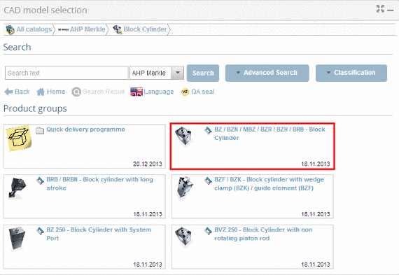
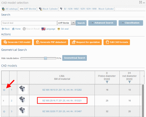
At directory level
 select product groups as long as a concrete assembly
  or concrete single part
  has been specified. Select the desired part by clicking into the option button before the desired row.
 -
Click on the part description in order to reach the variable view.

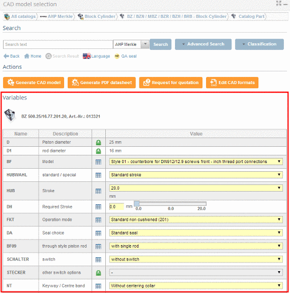
-> You will recognize the value range fields based on their yellow background color.
There are different types of value range fields:- List fields
Using the arrow open the value range field and select the desired value.

Then select the desired value.

- Input fields or selection via slider
Enter the desired value manually or set it using the slider in the given area.
Note
Inputs outside of the allowed value range are automatically corrected.
- Value range fields with images
Some catalogs support images for variant selection.
Click on the image in order to set another value.
-> A dialog opens for choosing the characteristic per image.
Select the desired variant by clicking on the image.
-> It is reloaded into the variable view.
If you do not want to take over the changes, click on x.
The part is now completely specified.
Permalink | 0 comments, 0 likes, 7,726 viewsWas this answer helpful? -
-
Follow the steps listed below to define the characteristic of the part: Make sure that you are in the dialog area 3D CAD ...
Follow the steps listed below to define the characteristic of the part:
-
Make sure that you are in the dialog area 3D CAD CATALOGS and search for the required part.
-
At directory level
select product groups as long as a concrete assembly or concrete single part has been specified and choose an assembly or a single part.
-
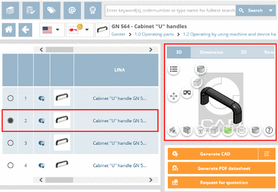
Define the characteristic of the part, by clicking into the option field of the desired row.
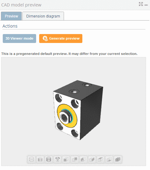
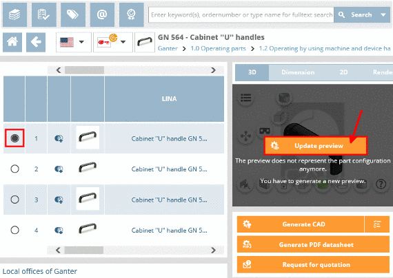
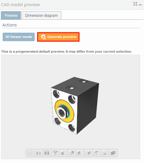
-> A default view of the selected model which may differ from the selected characteristic, is displayed under CAD model preview.
Note
If you want to view an exact replication of the characteristic, under Actions click on Generate preview.
-
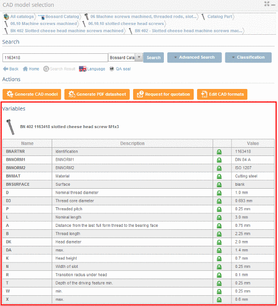
Switch to the variable view by clicking on the part description.
-
The variable view shows all important data of a specific characteristic in a compact form.
Permalink | 0 comments, 0 likes, 9,531 viewsWas this answer helpful? -
-
Follow the steps listed below to generate a PDF datasheet: Make sure that you are in the dialog area 3D CAD CATALOGS and select t...
Follow the steps listed below to generate a PDF datasheet:
- Make sure that you are in the dialog area 3D CAD CATALOGS and select the desired catalog.
- At directory level
 select product groups as long as a concrete assembly
 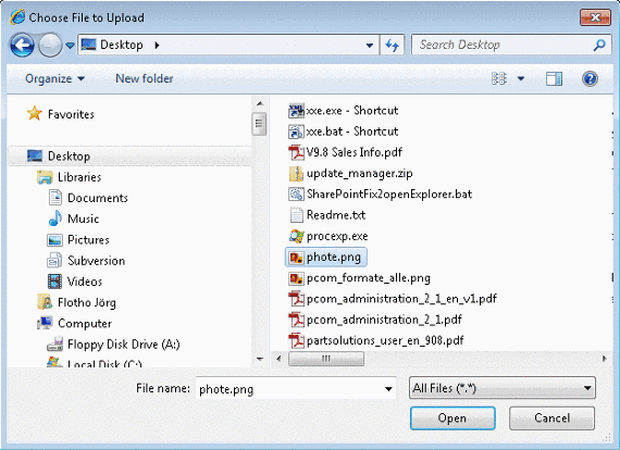 or concrete single part
  has been specified.
-> As soon as a concrete row has been determined, a 3D view and dimensional drawings are loaded under CAD model preview.
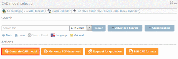
- Under Actions, click on Generate PDF datasheet.
- The information dialog Generation CAD models opens.
Note
If the CAD model shall be generated in several formats under Format selection there is the possibility to choose the format PDF Datasheet additionally. By holding down the CTRL key, you can make multiple selections.

- Under Actions, click on Generate CAD model.
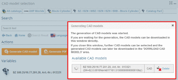
- The information dialog Generating CAD models opens.
-> The generation was started.
The following symbols show the generation status: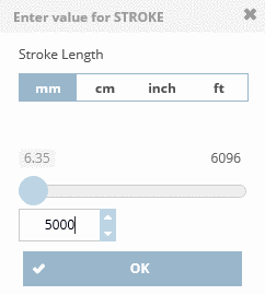 Active generation
 Generation erroneous
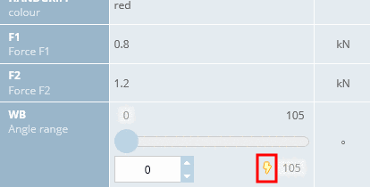 Generation successfull. Part ready for download.
Note
The pregenerated 3D PDF corresponds to a sample part (created for a mid-row with standard setting) and may differ from your selected part.
Permalink | 0 comments, 0 likes, 9,203 viewsWas this answer helpful? -
Follow the steps listed below to send a request for quotation: Make sure that you are in the dialog are 3D CAD CATALOGS and sele...
Follow the steps listed below to send a request for quotation:
- Make sure that you are in the dialog are 3D CAD CATALOGS and select the desired catalog.
- At directory level select product groups as long as a concrete assembly or concrete single part
 has been specified.
-> As soon as a concrete row has been determined, a 3D view and dimensional drawings are loaded under CAD model preview. - Under Actions click on Request for quotation.

-> The dialog for inputting your quotation request opens.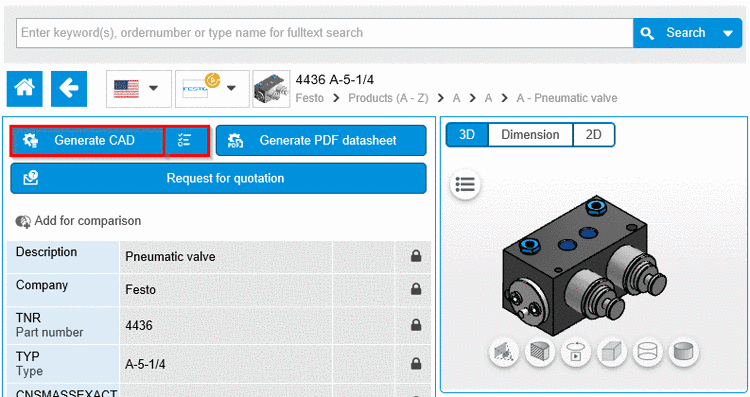
Fill in the input fields completely and click on Send request, to send the request. 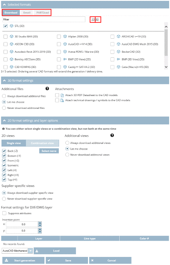
Note
In order to get a preview of your enquiry click on Preview request.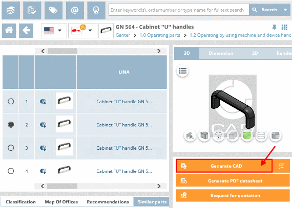
-> A dialog box with a preview of the request opens.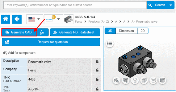
- As soon as the e-mail was sent, you will receive the confirmation Email has been sent successfully.

Permalink | 0 comments, 0 likes, 8,256 viewsWas this answer helpful? -
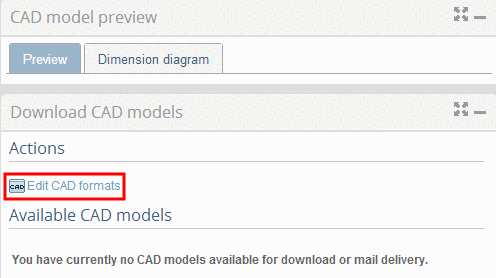
Under 3D CAD CATALOGS you have the possibility to chooses CAD formats and to define the handing over mode into the CAD system. 1. ...Under 3D CAD CATALOGS you have the possibility to chooses CAD formats and to define the handing over mode into the CAD system.
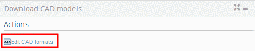
1. Make sure that you are in the dialog area 3D CAD CATALOGS.2. On the right side under Actions, click on Edit CAD formats

-> The following dialog are shows up:
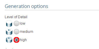
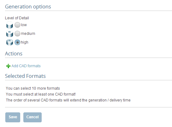
- Generation options (Level of Detail)
- Selected Formats (Add CAD formats)
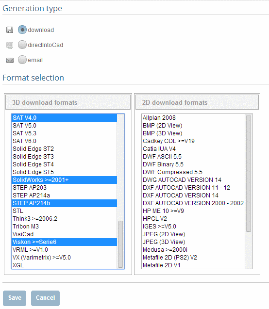
 3. Click on Add CAD formats.
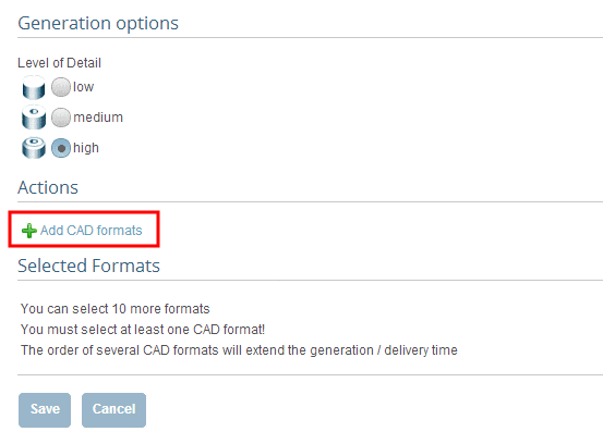 -> The settings area for Generation type and Format selection opens.
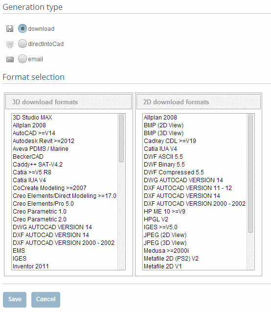 4. First determine the desired generation type. Click into the desired option field.
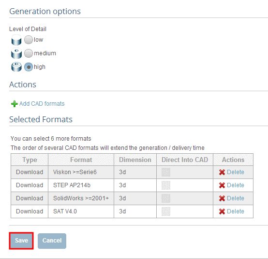
-> In the dialog area Format selection select a format or several formats.5. Click on Save.
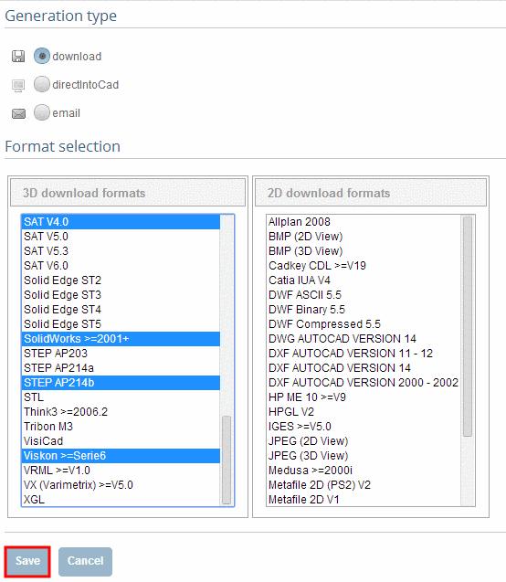
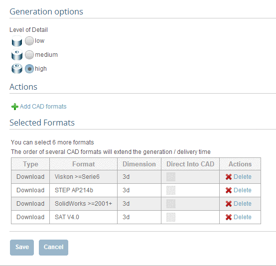
-> The view changes back to the dialog area Generation options / Selected formats.
In the dialog area Selected Formats you can see your current selection.
In addition to that under Actions you can define the Level of Detail. 6. Confirm your entries with Save.
 Permalink | 0 comments, 0 likes, 9,254 viewsWas this answer helpful?
 -
As soon as a part has been specified, the 3D preview shows up in the CAD model preview area CAD model preview. NoteA pregenerated d...
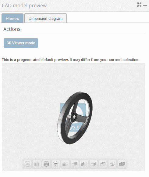
As soon as a part has been specified, the 3D preview shows up in the CAD model preview area CAD model preview.
Note
A pregenerated default preview is shown, which may differ from your current selection. If you want to see the fitting 3D view, that matches your characteristics, click on Generate preview in the Actions dialog ara.
The following explains the individual buttons of the 3D view:
Permalink | 0 comments, 0 likes, 2,342 viewsWas this answer helpful? -
Follow the steps listed below to generate your desired part: Make sure that your are in the dialog area 3D CAD CATALOGS&nbs...
Follow the steps listed below to generate your desired part:
- Make sure that your are in the dialog area 3D CAD CATALOGS and select the desired catalog.
-
At directory level
 select product groups as long as a concrete assembly
  or concrete single part
  has been specified.
-> A soon as a concrete row has been determined, a 3D view and dimensional drawings are loaded under CAD model preview.
-
In the dialog area Download CAD models under Actions define the generation type and the desired CAD formats by clickingEdit CAD formats.
-
The information dialog Generating CAD models opens.
Permalink | 0 comments, 0 likes, 8,799 views0% users marked this FAQ as helpful.|2 votesWas this answer helpful? -
Follow the steps listed below to reach your desired part: Make sure that your are in the dialog area 3D CAD CATALOGS. Select th...
Follow the steps listed below to reach your desired part:
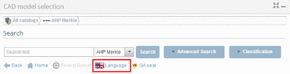
-
After you have selected a catalog, you may now select the catalog language.
-
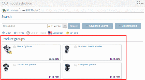
At directory level
select product groups as long as a concrete assembly or concrete single part has been specified. -
As soon as a concrete row has been determined, a 3D view and dimensional drawings are loaded under CAD model preview.
-
Define the characteristic of the part, by clicking into the option button before the desired row.
-
Variable view (possibly set value ranges)
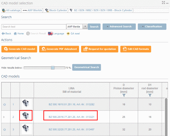
In order to reach the variable view, click on the part link or preview image.
-> You can now see all variables in list form.
In case value range fields are available - you will recognize this by the yellow-highlighted fields - use the arrow
 button in order to open these fields and select the desired value and simply enter it directly into the input area (alternatively also possible using a slider).
Permalink | 0 comments, 0 likes, 6,468 views100% users marked this FAQ as helpful.|1 voteWas this answer helpful? -
Under 3D CAD CATALOGS you have the possibility to choose CAD formats and to define the handing over mode in the CAD system. &n...
Under 3D CAD CATALOGS you have the possibility to choose CAD formats and to define the handing over mode in the CAD system.
-
-> The settings area for Generation type and Format selection opens.
-
First determine the desired generation type. Click into the desired option field.
-
Select a format or several formats. By holding down the CTRL key, you can make multiple selections.
Note
Max. 10 formats (in total for all generation types) is possible.
-
-> The view changes back to the dialog area Generation options / Selected formats.
In the dialog area Selected formats you can see your current selection.
-
Confirm your entries with Save.
Note
You can now repeat the format selection for another generation mode if desired.
Go back to Add CAD formats.
-> The current format selection is shown.
Permalink | 0 comments, 0 likes, 1,569 views0% users marked this FAQ as helpful.|1 voteWas this answer helpful? -
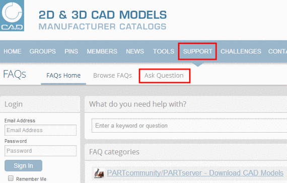
If you have forgotten the e-mail address which you have chosen during the registration please contact the support team via Ask Quest...
If you have forgotten the e-mail address which you have chosen during the registration please contact the support team via Ask Question in the FAQ area.
Permalink | 1 comment, 0 likes, 1,537 viewsWas this answer helpful? -
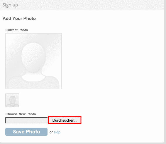
Log in with your access data and click on the button My Profile. On the right side, under Profile Options, cli...
-
Log in with your access data and click on the button My Profile.
-
On the right side, under Profile Options, click on Edit My Profile.
Permalink | 0 comments, 0 likes, 8,483 viewsWas this answer helpful? -
-
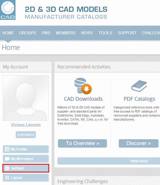
1. Log in with your access data and click on the button Settings. 2. Click inside the field Email Address and enter your new e-m...
1. Log in with your access data and click on the button Settings.
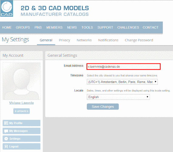
2. Click inside the field Email Address and enter your new e-mail address.
3. Confirm the data by clicking the button Save Changes.
-> The confirmation Settings were successfully saved is displayed.
Permalink | 2 comments, 0 likes, 8,454 viewsWas this answer helpful? -
Overview to the quality characteristics Gold Quality Seal Available in many languages Levels of detail included (LOD...
-
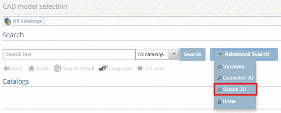
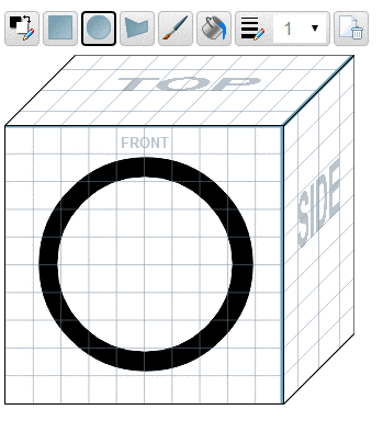
You can conduct a search based on self-drawn sketches. NoteFor a successful search, the part should be represented by at least 2...
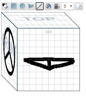
You can conduct a search based on self-drawn sketches.
Note
For a successful search, the part should be represented by at least 2 views (for example: top, right).-
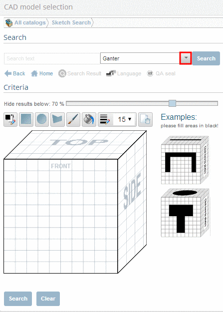
Open the list field by arrow button and select the catalog which you want to search through.
-
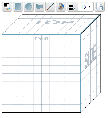
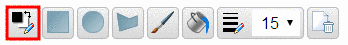
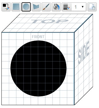
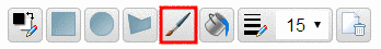
In order to draw the first sketch, click on the desired view (Top, Front, Side).
-
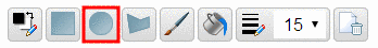
With your left mouse button, click into the center of the sketch and pull open a black circle by holding down the left mouse button.
-
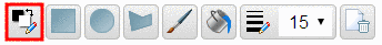
With the left mouse button, click into the midpoint of the sketch and pull open a smaller white circle whilst holding down the left mouse button.
-
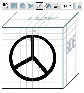
Click into the next view box in order to make your second sketch. Draw a second version of the hand wheel. The settings are already set correctly.
-
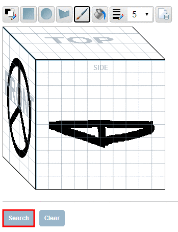
Note
After a search was conducted, the created sketches are saved and are available for use upon next launch (in the current situation they are available for use until you log off)
Permalink | 0 comments, 0 likes, 1,549 views100% users marked this FAQ as helpful.|1 voteWas this answer helpful? -
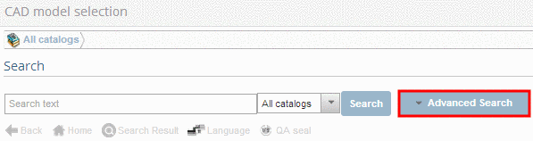
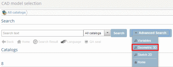
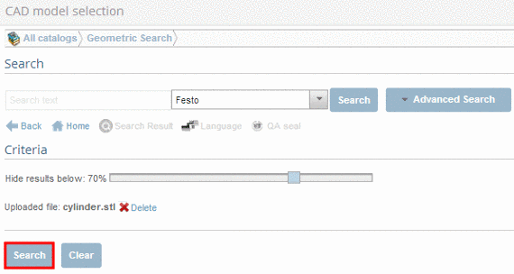
Click on Advanced Search. -> A drop down menu opens. Then select Geometric 3D. Using the arrow button, op...
-
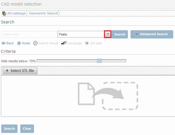
Using the arrow button, open the list field and select the desired catalog.
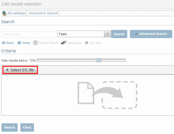
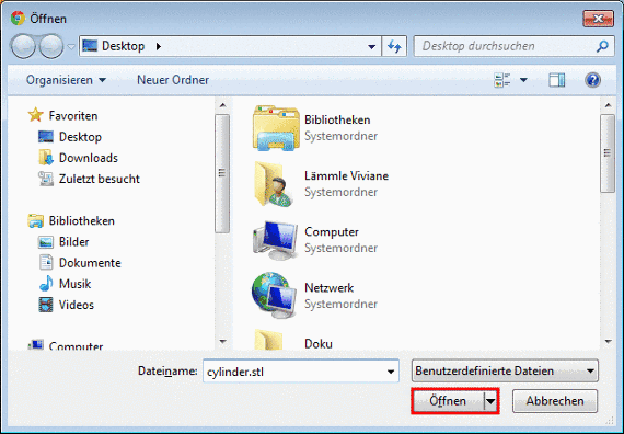
-
Select the desired file. Afterwards click on Open, in order to upload the file.
Permalink | 0 comments, 0 likes, 922 viewsWas this answer helpful? -
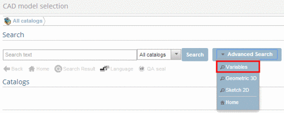
For some catalogs the variables search is possible; otherwise a respective notice is given. Click on Advanced Search. ...
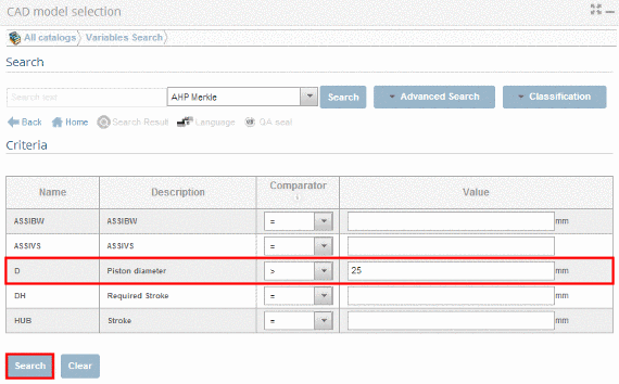
For some catalogs the variables search is possible; otherwise a respective notice is given.
-
-
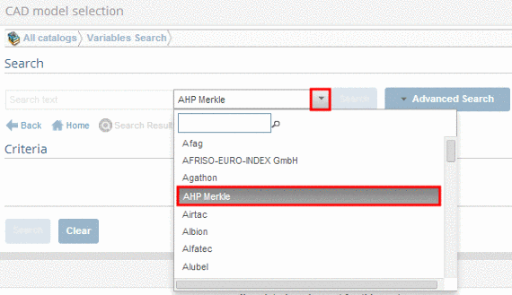
Open the list field under Search and select the desired catalog.
-> Under Criteria those variables will be displayed that are common to all parts.
-
In the list field select a mathematical operator and set the desired filter values. Then click on Search.
-> Under Search Results all parts that correspond to the filter variables are listed.
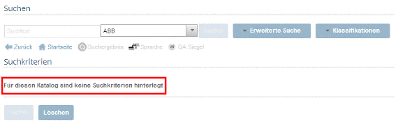
If there are no search criteria set for a catalog, the following message shows up:
Permalink | 0 comments, 0 likes, 799 viewsWas this answer helpful? -
-
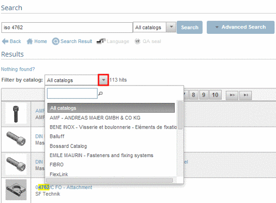
Enter the search text and click on Search. NoteThe number of characters must be at least 3.Part string search i...
-
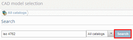
Enter the search text and click on Search.
Note
The number of characters must be at least 3.
Part string search is possible.
Wildcard search with '*' is possible.Boolean operators
You can increase the efficiency of search queries by using boolean operators. Use the operators listed below with the explanations given by the examples.
AND
Search for documents in which both terms come up.
Example: screw AND din AND galvanic
OR
Search for documents in which one of the terms comes up.
Example: screw OR nut
NOT
Exclude a term.
Example: nut NOT screw
+
Search with specific need for a term.
Example: +din screw
*
Search with placeholder for several symbols.
In order to find "groove ball bearing", the following example may be used:
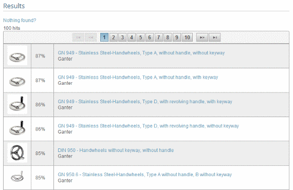
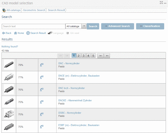
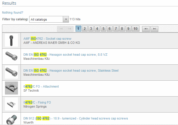
Example: grooves*-> The found parts are listed under search results.
-> In order to keep the number of results at a minimum, you can filter by catalogs.
-
Using the arrow button, open the list field and select the desired catalog.
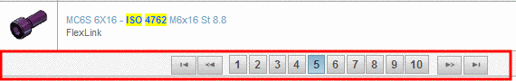
-> You can look through large amounts of search results using either the page numbers or the arrow buttons.
-
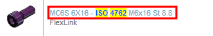
To load the desired part, click on the part description (link).
Permalink | 0 comments, 0 likes, 639 viewsWas this answer helpful? -
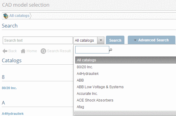
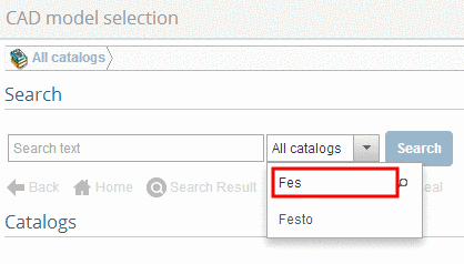
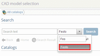
-
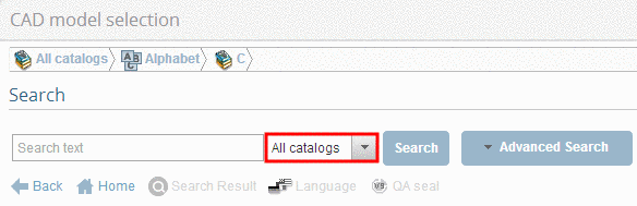
Click on All catalogs.. -> A drop down menu appears. Click into the input field. Type in one or several initia...Permalink | 0 comments, 0 likes, 751 viewsWas this answer helpful?
-
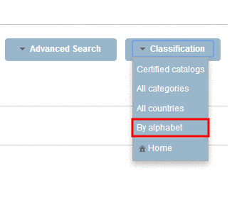
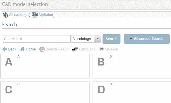
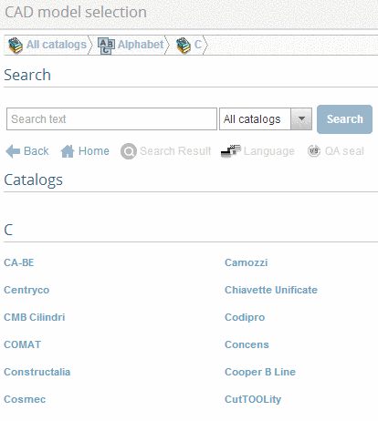
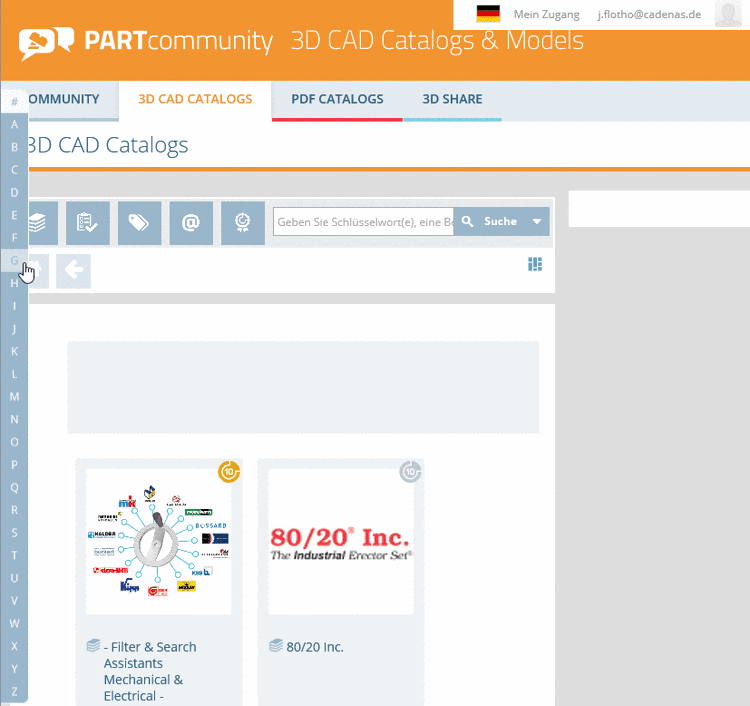
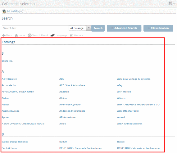
Click under Classification on By alphabet.. Click on a letter. -> Only catalogs with this first letter ar...
-
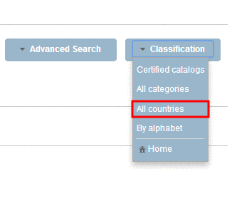
Click on Classification Afterwards choose in the drop down menu All countries.. Click on a country of your choi...
-
Click on Classification Afterwards choose in the drop down menu All countries..
-
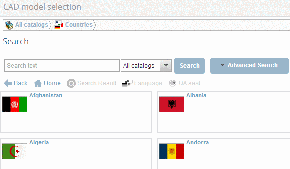
Click on a country of your choice.
-> Only catalogs are shown, which contain deliverable components for the chosen country.
-
Choose the desired catalog now.
-> You`ll reach the first selection level of the chosen catalog directly.
Permalink | 0 comments, 0 likes, 615 viewsWas this answer helpful? -


 Back you reach the previous level.