Login
Our 3D CAD supplier models have been moved to 3Dfindit.com, the new visual search engine for 3D CAD, CAE & BIM models.
You can log in there with your existing account of this site.
The content remains free of charge.

Top Links
Categories


Search FAQs
Most Recent FAQs
-
0 comments, 0 likes, 3,606 views100% helpful.
-
0 comments, 0 likes, 4,837 views100% helpful.
-
0 comments, 0 likes, 10,782 views
Most Viewed FAQs
-
0 comments, 0 likes, 129,559 views0% helpful.
-
0 comments, 0 likes, 25,490 views
-
0 comments, 0 likes, 21,546 views18% helpful.
FAQs
-
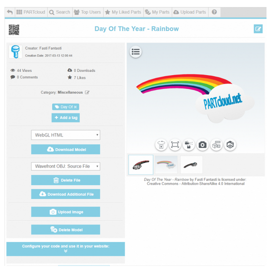
1. Go to your published 3D model on PARTcloud.net (3D SHARE) 2. Click on "Configure your code and use it in your website". Als...
1. Go to your published 3D model on PARTcloud.net (3D SHARE)
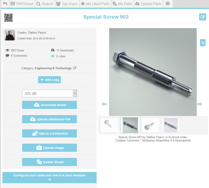
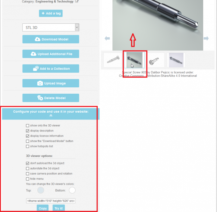
2. Click on "Configure your code and use it in your website". Also, click on the render to be visible, not 3D model (upper red box).
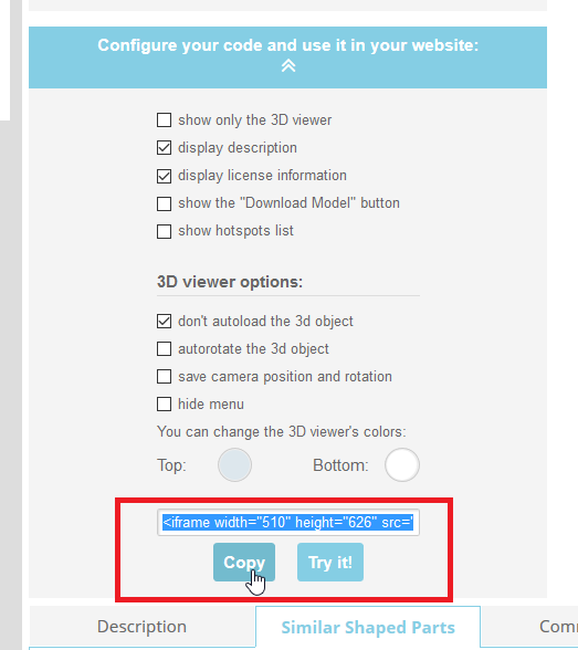
3. Click on "Copy" and the link will become blue
4. Click on "Community" (upper-left)
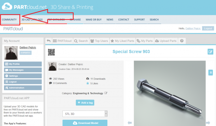
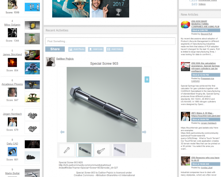
5. Once you are on homepage, just "Paste" it on "Post Something..." and you will see the link of your 3D model. Click on "Share".
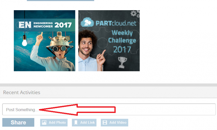

6. Your 3D model/render should be published on homepage now and it will get more attention like that!
 Permalink | 0 comments, 3 likes, 5,997 views100% users marked this FAQ as helpful.|9 votesWas this answer helpful?
 -
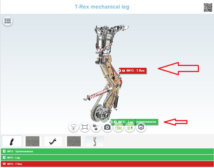
With the so-called HotSpot function, additional diverse information can now be linked with a preview of the uploaded component. Those 3...
With the so-called HotSpot function, additional diverse information can now be linked with a preview of the uploaded component. Those 3D CAD models become an interactive encyclopedia for engineers and members of the PARTcloud.net sharing community.
Besides videos and animated graphics, members of the community can also provide descriptions of the 3D CAD model and explain their own designs. The advantage is also shown with the sharing or embedding of the 3D CAD model in other websites: The information remains unchanged and engineers can obtain a first impression at once.
How to do it? It is very simple, just follow these guide lines:
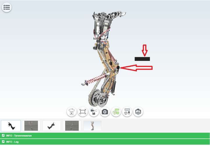
1. Once your 3D model is uploaded on PARTcloud.net, a HotSpot can be added. Click on the icon "HotSpot Mode".
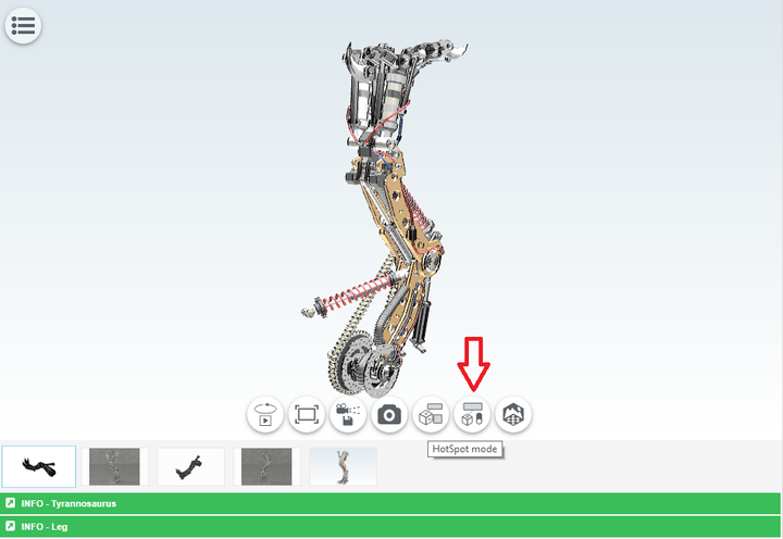
2. Choose the HotSpot location on your 3D model and click to confirm it. The "black box" is a place where the title will be shown.
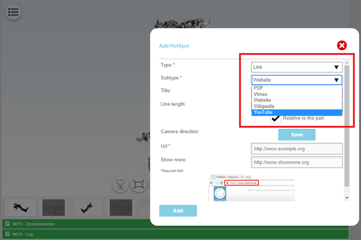
3. Choose among options depending on what you would like to add. A new window appears where the information can be selected that is to be filed. Users then have a choice between texts, links, images, videos and manufacturer catalogs. The latter shows engineers, for example, which standard parts were used in the design. In this case, we will use "Link" and then "YouTube" in order to show a video clip. If you want to add an article, you can choose "Wikipedia" - it is all up to you.
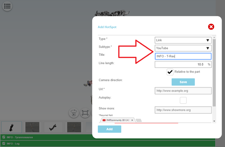
4. Add the title of info you would like to provide.
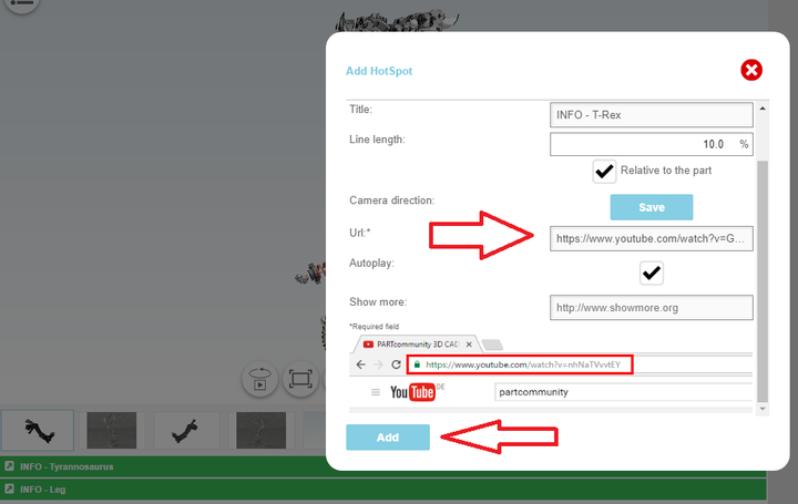
5. Find what you are looking for (in this case, a video clip from YouTube) and copy-paste the link. Click on "Add".
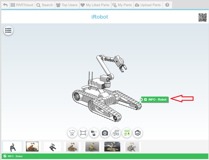
6. The HotSpot should appear beside your 3D model. You can add as many HotSpots as you like. We added one more in this case (on bottom) to make it educational and more interesting like that.
7. Click on it and you can watch that specific YouTube video clip. You can also click on YouTube to take you directly there (black arrow). Once again, you can add any other HotSpot depending on what you would like to show: Wikipedia article, PDF catalog, Vimeo, photo, website, etc.
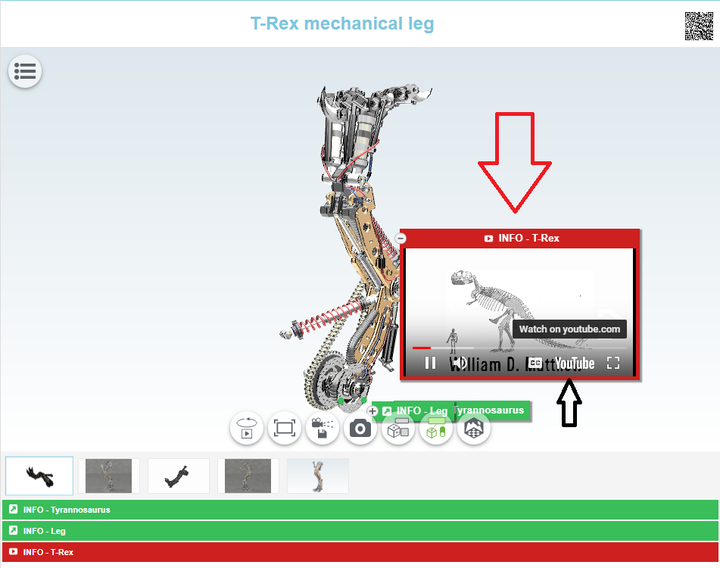
https://www.youtube.com/watch?v=gY6o2_8Fqu8
Permalink | 0 comments, 3 likes, 8,742 views100% users marked this FAQ as helpful.|9 votesWas this answer helpful? -
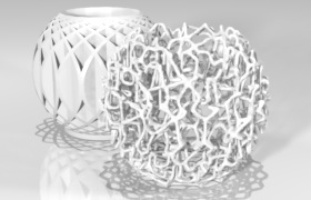
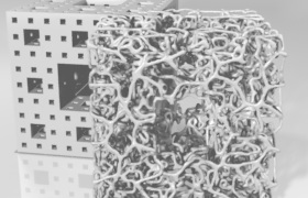
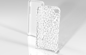
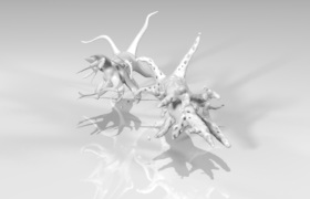
About this service - http://www.voronator.com/ Supported formats Currently supported formats for input are:...
About this service - http://www.voronator.com/
Supported formats
Currently supported formats for input are:
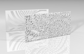
As output format we provide STL and PLY (both binary only).STL Stereolithography binary and ASCII PLY Stanford Polygon Library DAE Collada OBJ Wavefront Object OFF Object File Format The result is rubbish!
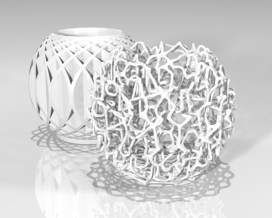
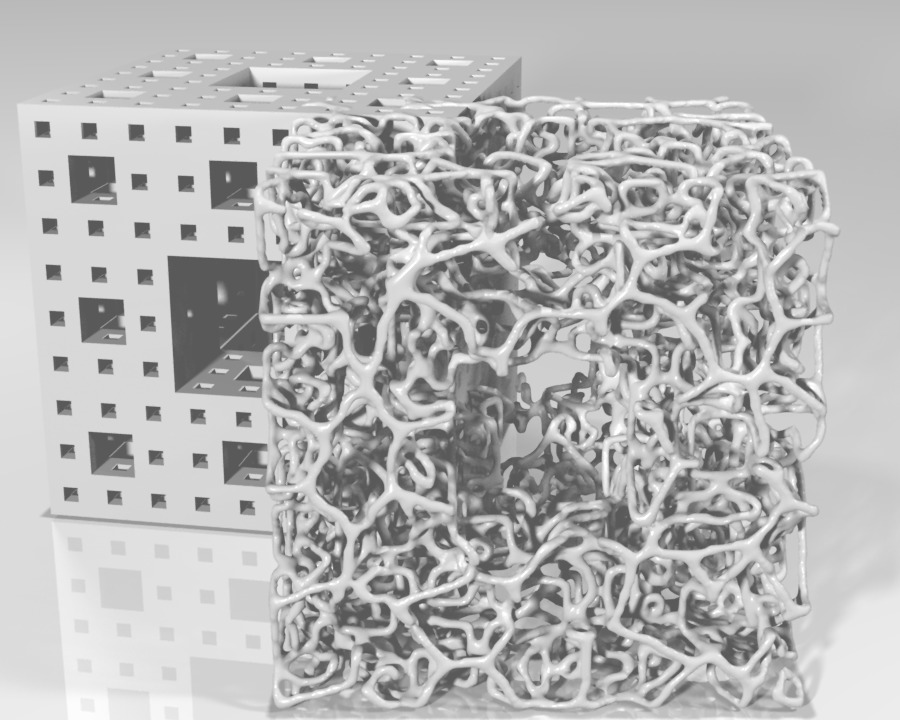
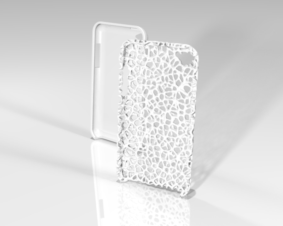
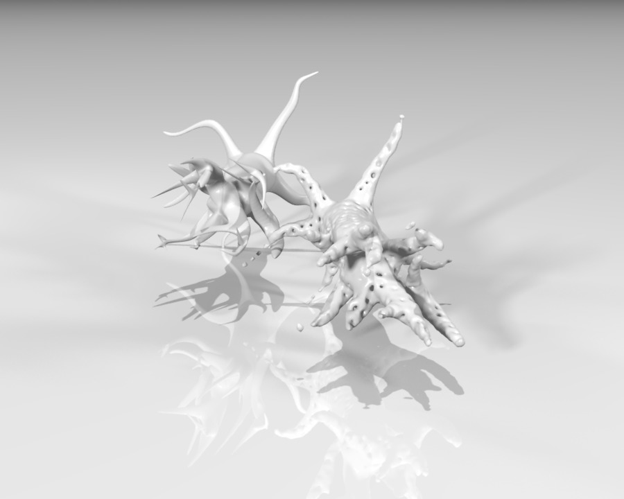
Yeah, that can happen. Not all models are suitable for our Voronoization process.
Take a look at the following models to get an idea what kind of models will not work.
Models with thin solids or convoluted structures will not work with our Voronoization process.

 Permalink | 0 comments, 2 likes, 6,777 viewsWas this answer helpful?
 -
1. Register on PARTcommunity.com 2. Upload your 3D model on 3D SHARE - PARTcloud.net 3. Choose "Cha...
1. Register on PARTcommunity.com
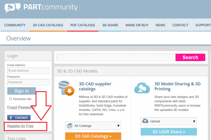
2. Upload your 3D model on 3D SHARE - PARTcloud.net
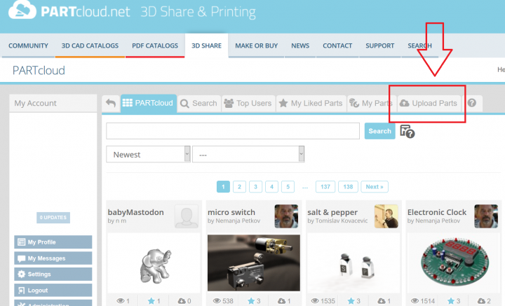
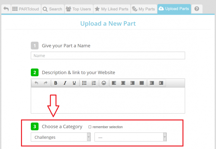
3. Choose "Challenges" category (no need to choose subcategory). First you upload files, then renders (Upload Image).
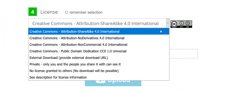
4. Choose the right license depending on your choice.
5. Done. You can upload as many 3D models as you wish for the Weekly Challenge and good luck!
Permalink | 3 comments, 1 like, 7,095 views88% users marked this FAQ as helpful.|8 votesWas this answer helpful? -
http://touchterrain.geol.iastate.edu/ What is Touch Terrain? Our TouchTerrain web application creates 3D terrain model files that can b...
http://touchterrain.geol.iastate.edu/
What is Touch Terrain?Our TouchTerrain web application creates 3D terrain model files that can be printed on a 3D printer. You select the area you want to print, decide which Digital Elevation Model (DEM) you want to use, set some print parameters and let the app do all the work. When it's done, you download the 3D model file(s) (STL or OBJ format) and print it out on your 3D printer or send it to an online 3D print service.
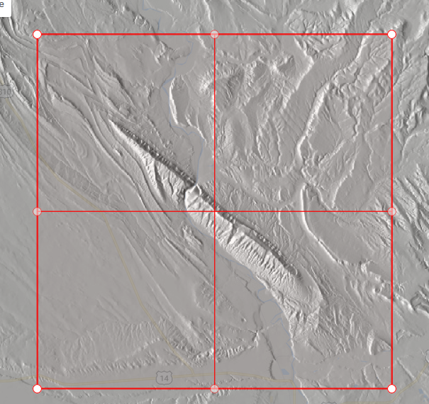
Area selection (hillshade):
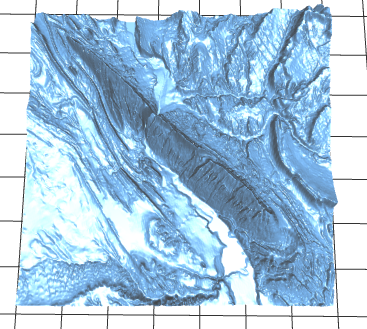
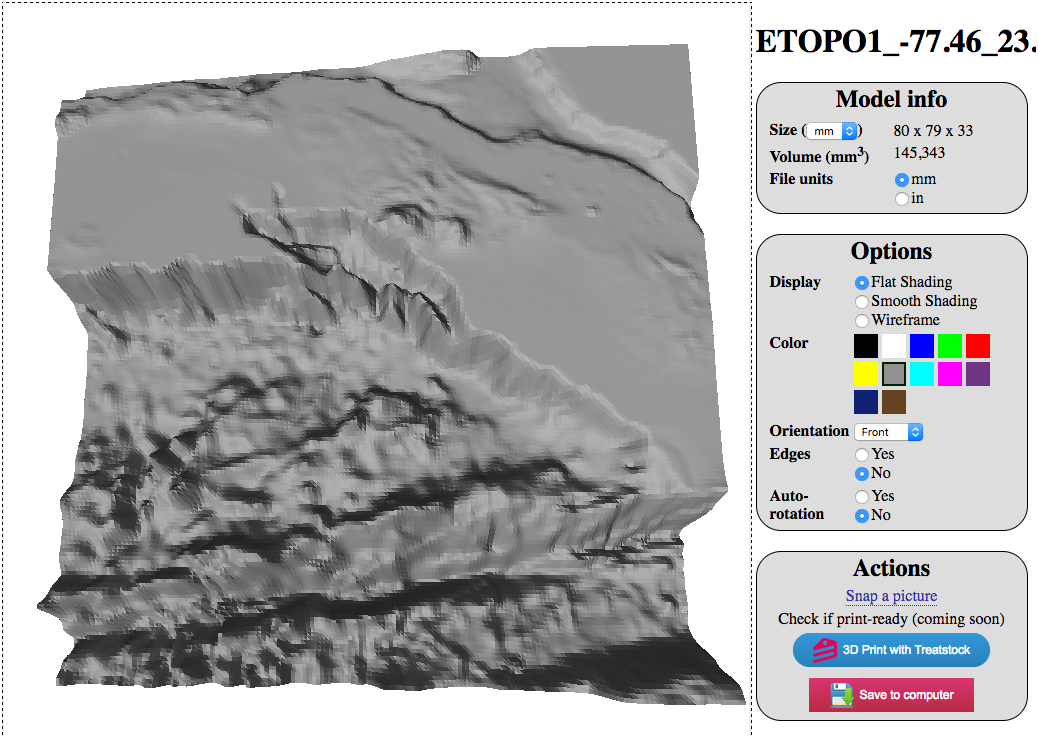
3D digital model (link to live viewer):
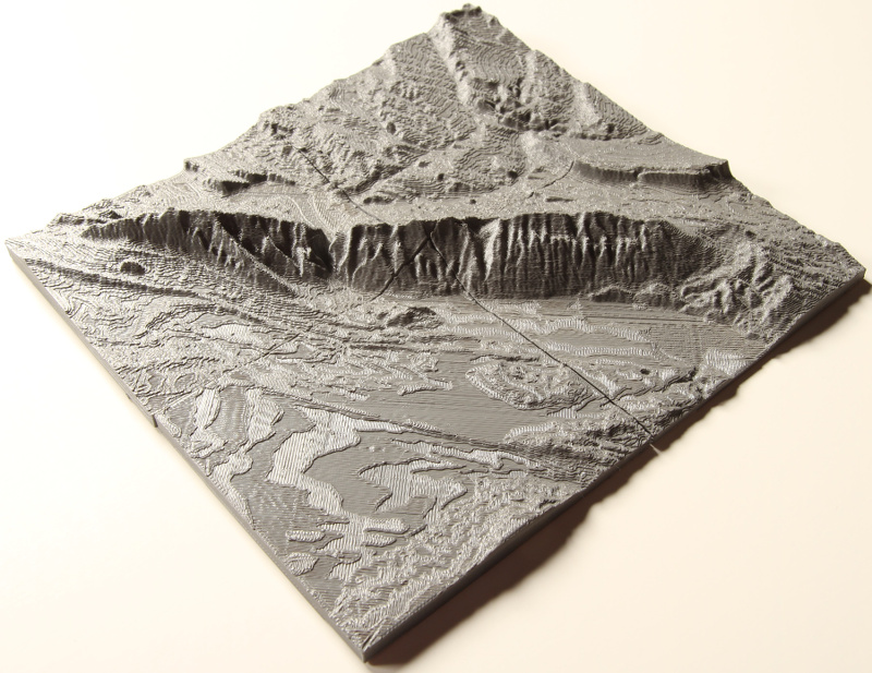
3D printed model:
This app is developed by Chris Harding and Franek Hasiuk of the Geofab lab at Iowa State University. It's use is free of charge but please understand that it is still in early development and so may not always work perfectly.
How to use the TouchTerrain app
Let's say you want to 3D printable terrain file(s) for a certain area. First, you need to find this area on the Google Map.
Moving around the google map
- Move the Transparency slider to the left to hide the hillshade layer for now.
- Click on the - or + button the in the lower left corner to zoom out or in. (Or: use your mousewheel).
- Left click and drag your mouse to pan the map.
- Switch to different types of google maps via the buttons in the upper left corner: streetmap, terrain map, satellite map
- Use zoom and pan until you find the desired area.
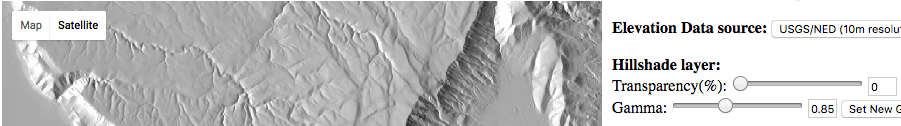
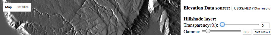
Using the hillshade layer
The hillshade layer shows topographic relief, which tends to bring out ridges, river beds, and other terrain morphologies. It's useful for finding interesting terrain features for printing. The hillshade layer overlays the Google Map (street map or satellite map); Move the Transparency (%) slider to "mix" both layers, the higher the % the more the Google basemap will come through:
0%
45%
70%
70%, with street map
You can further tweak the appearance of the hillshade layer by setting different Gamma Correction values, which affects the luminance of the hillshade. Low Gamma (< 1.0) values make for a generally darker hillshade but can be helpful to bring out minute details, especially in relatively flat terrain. Unlike with the Transparency slider, where change is instantaneous, you have to click on Set New Gamma Value to see the change (because it requires server-side processing).
0.3
1.0
2.0
Choosing an Elevation Data Source
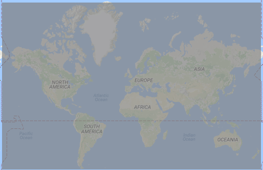
TouchTerrain offers several types of Digital Elevation Data (DEM) rasters, which differ in resolution and area coverage. Resolution refers to the real-world size of each raster cell (pixel), e.g. in the USGS/NED DEM raster, each cell is approximately 10 x 10 m. However, NED only covers the US - areas outside the US are covered at lower resolutions. After selecting a different Elevation data source, the areas covered by it will be shown via the grey hillshade layer:
USGS/NED:
~10 m resolution,
US lower 48 states onlySRTM GL1:
~30 m resolution,
Worldwide up to 60 degrees latitude
GMTED 2010:
~90 m resolution,
Worldwide, onshore-only
ETOPO1:
~1 km resolution,
Worldwide - including offshore (bathymetry)
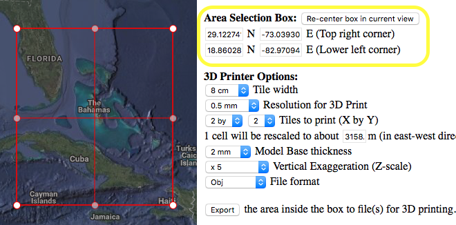
Selecting an area to print
Once you've decided on a general area, click on Re-center box in current view. This will show a red Area Selection Box, outlining the area you will 3D print.
- Click inside the box and drag - this will move the box without changing the size.
- Click on one of the small white circles and drag - this will resize the box.
- If you lose the box when moving around the map, press Re-center box in current view again.
- The lat/long coordinates of the top right and lower left corner of the selection box are shown as well. (But, you cannot change the box by typing in coordinates …)
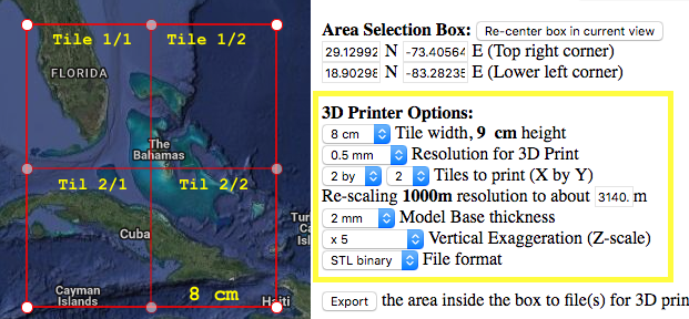
Setting the 3D Printer Options
This configures how the selected area will be converted into 3D model files for later printing.
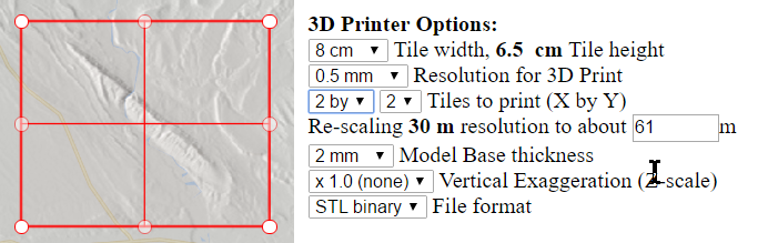
- Tile width: The width of each tile after it's file has been printed out. Here, the selection box is divided into 4 tiles ( 2 x 2). The width of each of the 4 tiles set to 8 cm, their height has been calculated to 9 cm. To make a decision you need to know the approximate size on your printer's build plate.
- Resolution: Again, you will need to have some knowledge about the XY precision of your printer. This number is limited by the realistically smallest vertical distance (in mm) your printer can move. As finer resolutions leads to longer processing and print times and larger 3D model files, it is advisable to start with a rather coarse resolution (something like 20 x the finest XY precision of the printer given in your manual) and go to a finer resolution if the results lack desired details. Conceptually, this corresponds how the printer moves along an internal grid - for a 80 mm x 90 mm tile, 0.5 mm per step results in a 160 x 180 grid.
- Tiles to print: the number of tiles that divide the Selection box into smaller areas. Each tile has the same size (width x height)
- Re-scaling: Depending on the values for tiles and printer resolution, the original DEM raster will be re-sampled to approximately this resolution before creating the 3D models from it. This is directly related to the aforementioned grid. Here, the original DEM raster has a 1000 m resolution; however, the requested 160 x 180 grid corresponds to a coarser resolution of about 3140 m. Using this lower resolution means less processing and smaller files. But, if you wanted to, you could get closer to the original 1000 m resolution by either making the tiles larger (e.g. set the tile width to 10 cm), use more tiles (3 by 3) or lower the print resolution (e.g. to 0.3 mm). However, make sure that your do not rescale drastically below the original resolution, in this case below 1000 m.
- Model base thickness: a thin base will be put beneath the model to prevent having a hole at the lowest elevation. The thickness should be at least be four times as thick as a typical layer from your printer to ensure good coverage.
- Vertical Exaggeration (z-scale): the elevation is multiplied by this factor before printing. A z-scale of x 1 results in no distortion. Z-scales larger than one are useful to bring out details in comparatively flat terrain.
- File format: The type of 3D model file created. STL is the standard format for 3D printers. STL binary is prefered for its small file size.
Understanding the linkage of tile size, tile number, source DEM resolution and 3D print resolution
It is useful to understand how these four parameters are linked to create good quality 3D models. You probably want your 3D printer models to show as much detail as possible, which means setting the parameters in a way that the re-scaled resolution is close to, but not lower, than the source DEM resolution. As this can be a bit of a juggling act, here's an example scenario:
Let's assume you want to create a tiled model with the SRTM GL1 DEM source, for which each cell is 30 x 30 m. With 4 tiles, each 8 x 6.5 cm and a resolution of 0.5 mm, the 30 m cells need to be rescaled (resampled, interpolated) to a 61 m cells for 3D printing. This means that as the 3D printer moves in 0.5 mm steps, it jumps (roughly) 60 m in reality, so the printed model would have less detail than it could, given the original DEM data resolution of 30 m. That's not necessarily a bad thing, you're just not getting the degree of terrain details that the original DEM sources data provides.
If you wanted to get a print with better detail, there are several parameters you could tweak:
- Use a finer 3D printer resolution (i.e. lower the mm number). Using 0.25 mm instead of 0.5 mm yields a rescaling to 30.5 m from the original 30 m resolution, i.e. this printout would show better detail than the 60 m version we had before. However, you have to make sure that your 3D printer can actually realize this finer resolution effectively, something that may requires you to print both versions and compare the end results. It may well turn out that the finer resolution model does not actually look any better than the coarser version, in which case you might as well stick with the coarser resolution.
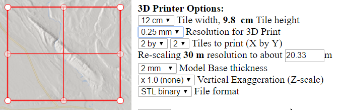
- Increase the tile size (cm). With a 12 x 9.8 cm tile size (but again using 0.5 mm), the print model would be rescaled from 30 m to 40.66 m. The full model would be physically larger (24 x 19.6 cm) and its detail noticeably better than the model with the 61 m resolution:
- Increase the number of tiles. Setting the size back to 8 x 6.5 cm, again using a 0.5 mm print resolution, but this time using 3 x 3 tiles, rescales from 30 m to 40.7 m. Very similar to the case above - again the full model would be 24 x 19.5 cm with better detail, but you would have to print out 9 tiles instead of 6 tiles.
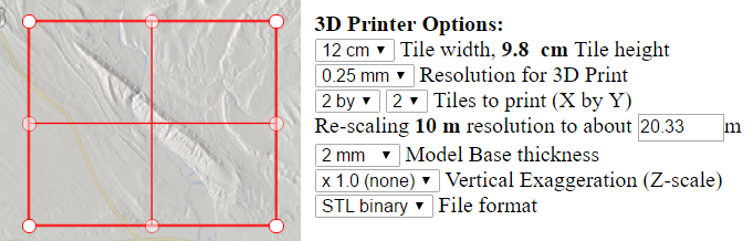
By now you can probably see how these parameters interact. You could, of course, change multiple parameters at once, e.g. set larger tiles (12 x 9.8 cm) and use a finer 3D print resolution of 0.25 mm:
This results in a rescaling from 30 m to 20 m, which will print but is actually somewhat pointless. Resampling the original DEM resolution to 20 meters will not increase the information content, and you're unlikely to print a model with better details than using around 30 m. You will, however, wait a bit longer and get larger files, which is simply inefficient. In other words, you might as well try slightly coarser print resolutions (0.3, 0.35, etc.) until the rescale meter number is pretty close to 30 m.
However, depending where your area is located, you may have the option to switch to a higher resolution DEM source! For this area, we can switch to the 10 m USGS NED DEM data source, which, with the same settings rescales from 10 m to 20 m, which will in fact result in a truly more detailed printout.
To recap: Once you've selected your area you need to have some idea about the effective range of resolution your 3D printer can do (e.g. 0.5 mm is a bit coarse, 0.2 mm is very fine) and know the size of your build plate (e.g. you are limited to models less than 12 x 12 cm). Decide on a rough physical size of your final 3D printed map (i.e. all tiles put together should be about 40 x 40 cm). Set the number of tiles and the tile size and adjust the 3D printer resolution setting until it is around the original DEM resolution but not much below. To be clear, there's nothing wrong with ending up with considerably larger numbers, as in my 10 m => 20.33 m example from before, as long as you're happy with the total size of your final 3D printed map and the number of tiles you have to print.
Processing and downloading the 3D model files
- Once you're set the 3D print options, press Export.
- This will show the pre-flight screen (Processing started). Press the Start button once and wait.
- The server now creates your 3D model files, however, there's no progress indicator, your browser will simply show that it trying to connect. That's normal, just be patient.
- (Note: we found that Safari tends to time out for large models i.e. high resolution and/or a lot of tiles, but Firefox or Chrome are more patient …)
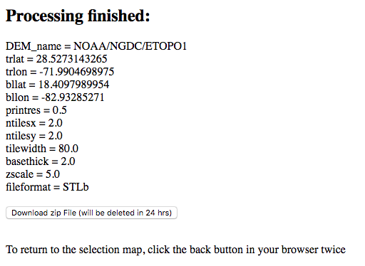
- Once processing has finished, you will see a summary screen. (Processing for this finished in about 60 seconds):
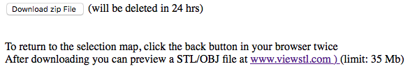
- Click the download button to download the zip file and unzip it. The unzipped folder will contain a 3D model file for each tile plus a log (text) file that summarizes the processing steps and detailed information about the DEM raster:
Checking the 3D model files
Before you start to print it's advisable to check the 3D models first. http://www.viewstl.com/ is a web site for uploading and previewing each tile. It also connects you to Treatstock, which will show a couple of online 3D print services.
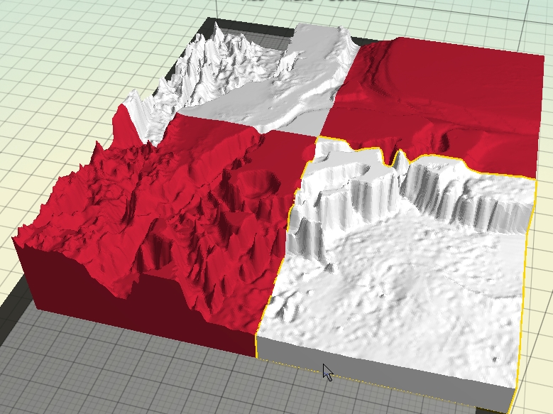
If you want to print yourself, your 3D print program (e.g. MakerWare desktop) will give you a 3D view of your model. Note that you should never need to scale-to-fit as each tile model already has a true mm-based size given by width, height and z-scale from the 3D printer options.If you want to preview how multiple tiles look when put together, add them one by one to MakerWare desktop but do NOT have them move to the center. The x/y coordinates of all tiles are set so that all tiles will naturally fit together! However, the tiles will very likely exceed your build plate size, which is OK as this is just a preview.
Here are the four ETOPO1 STL files downloaded earlier, shown in 2 different colors to prove they are separate models:
(TODO: list of other multi-stl file viewers)
Looking at the 3D models, you may find that you don't like something in the model, e.g. you want more or less z-scaling or a different tile configuration, etc. Simply click the Back button on your browser twice and you're back at the Map screen with the exactly the same values you had before you clicked Export. Changes things to your liking and try again.
3D printing the models
Restart MakeBot and add a single tile. This time, make sure it is put at the center of the build plate.
Permalink | 4 comments, 1 like, 13,686 views100% users marked this FAQ as helpful.|1 voteWas this answer helpful? -
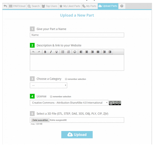
1.) Go to https://b2b.partcommunity.com/community/partcloud/index#!upload-parts Interesting: Choosing the right license
-
Please check the following points: - are you logged in on the partal with you account?- can the part be generated in other export format...
Please check the following points:
- are you logged in on the partal with you account?
- can the part be generated in other export formats?If your problem could not be solved please contact the support team
via Ask Question in the FAQ area.
Permalink | 0 comments, 1 like, 13,948 views33% users marked this FAQ as helpful.|9 votesWas this answer helpful? -
-> The activation link will be sent to the specified address automatically. Open the e-mail sent to you and activate your acc...
-
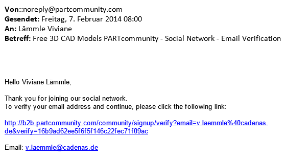
-> The activation link will be sent to the specified address automatically.
-
Open the e-mail sent to you and activate your account by clicking on the activation link.
-
Please check your spam folder if you have not received any activation link since the registration yet.
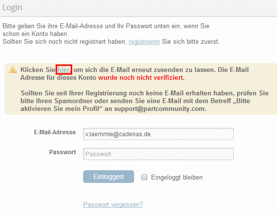
-> If you can't find the e-mail anymore you can request the activation link again.
-
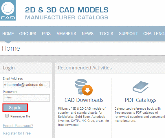
Enter your access data and click on "Login".
-
In order to request the activation link again click on "here".
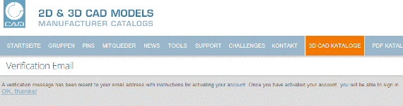
-> You will receive the confirmation „Verification Email“.
-
Open the e-mail sent to you and activate your account by clicking on the activation link.
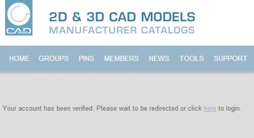
-> Afterwards you will receive the confirmation "Your account has been verified. Please wait to be redirected or click here to login“.
-> For further questions please contact the support team via "Ask Question" in the FAQ area.
-
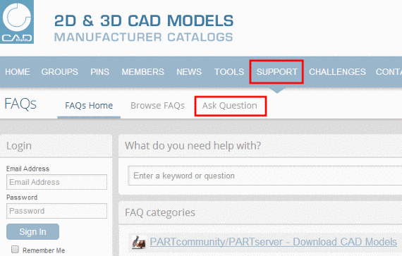
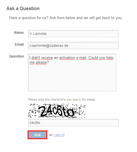
Click on "Support" and afterwards on "Ask Question".
-
To send the request, please fill out all input fields and click on "Ask".
-
Permalink | 0 comments, 1 like, 15,493 views60% users marked this FAQ as helpful.|5 votesWas this answer helpful? -
-
This is a video tutorial (YouTube) on how to upload a 3D model to PARTcloud.net done by our member Arcadeous Phoenix: https://ww...
-
1. Go to the specific group and click on More+ and then on Albums. 2. Click on Create Album. 3. Write the title and...
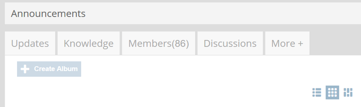
1. Go to the specific group and click on More+ and then on Albums.
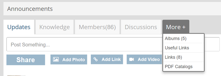
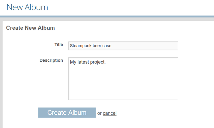
2. Click on Create Album.
3. Write the title and add a short description (you can add your YouTube, Facebook, Twitter or any other link).
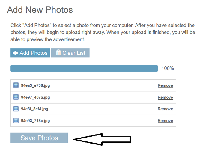
4. Add desired photos.
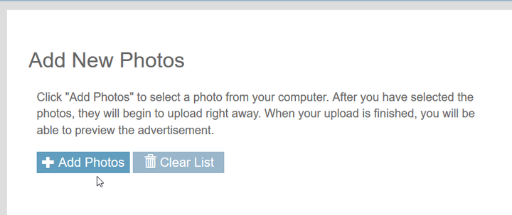
5. When all photos are uploaded, simply save photos. You photo album should be published now.
 Permalink | 0 comments, 0 likes, 4,837 views100% users marked this FAQ as helpful.|1 voteWas this answer helpful?
 -
ORIGAMI SIMULATOR ( 2017 ) DEMO HERE This WebGL app simulates how any origami crease pattern will fol...
This WebGL app simulates how any origami crease pattern will fold. It may look a little different from what you typically think of as "origami" - rather than folding paper in a set of sequential steps, this simulation attempts to fold every crease simultaneously. It does this by iteratively solving for small displacements in the geometry of an initially flat sheet due to forces exerted by creases. It calculates the geometry of folded or partially folded origami using a dynamic, GPU-accelerated solver; the solver extends work from the papers Origami Folding: A Structural Engineering Approach and Freeform Variations of Origami. It also supports an immersive, interactive VR mode using WebVR. More information about the solver and the app is being compiled into a paper and will be posted here soon.
Live demo here, code on Github.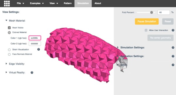 GIF
GIFThe Origami Simulator lets you simulate how any crease pattern will fold in 3D. Try it here.
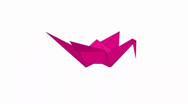 GIF
GIFFolding a traditional crane in one step in the Origami Simulator.
Crease patterns are uploaded into the app in SVG or FOLD formats. SVG crease patterns use color and opacity to set the direction and final fold angle of each crease. These patterns are triangulated and modeled as pin-jointed truss networks with additional angular constraints in the solver. At each step of the simulation, the displacements of nodes in the origami are calculated and used to update the visualization.
 GIF
GIFThis crease pattern was generated by Maze Folder, an app by Erik Demaine, Martin Demaine, and Jason Ku that creates crease patterns for any raised maze on a square grid. Based on the paper Folding Any Orthogonal Maze by the same authors.
This app uses a compliant dynamic simulation method to solve for the geometry of an origami pattern at a given fold angle. The simulation sets up several types of constraints: distance constraints prevent the sheet from stretching or compressing, and angular constraints fold or flatten the sheet. Each of these constraints is weighted by a stiffness - the stiffer the constraint, the better it is enforced in the simulation.
Cauchy strain or engineering strain is a unitless measurement of how much a material is being stretched or compressed under load. The app can be put into a strain visualization mode that illustrates the strain across an origami sheet by mapping it to a color from blue (no strain) to red (max strain). Visualizing strain gives a sense of how much the distance constraints in the origami pattern are being violated (i.e. how much the sheet is being stretched). The strain at each vertex is evaluated by averaging the percent deviation of all its distance constraints with adjacent vertices. This deviation is reported as a percent of the total length of the distance constraint to remove scaling effects.
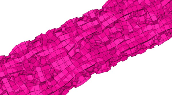
Strain map of folding waterbomb tessellation. The pattern tends to curl to minimize internal strain in the material.
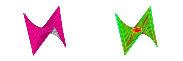 GIF
GIFSix-Pointed Hypar variant with strain map. This model was triangulated in an alternating asymmetric hinge triangulation based on the paper (Non)existence of Pleated Folds: How Paper Folds Between Creases.
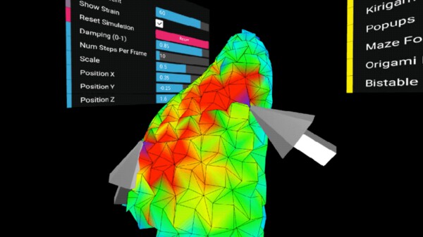 GIF
GIFDirect interaction with a Huffman Waterbomb tessellation in virtual reality. This app connects to virtual reality hardware via the WebVR api. In this mode, you can visualize the mesh folding in 3D and interact with it directly. Grab the mesh with both hands to see how it moves and watch internal strain propagate through the model. A longer VR demo video is on YouTube.
Typically, origami patterns are made from many straight creases, but by using curved creases it's possible to create more organic forms. Curved creases are simulated in the app by discretizing them into many small, straight segments - according to the paper Curved Folding.
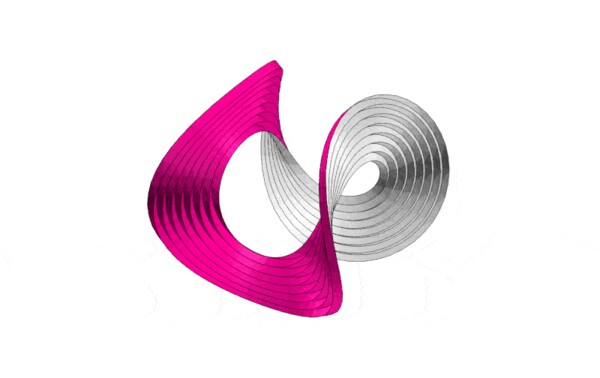 GIF
GIFHarmonics of a circular pleat origami, eventually resting in a low frequency configuration.
Kirigami is a variation on origami that incorporates cuts into a folding pattern. Many "popup" patterns used in cards or books are examples of kirigami. Green lines in crease patterns are treated as cuts when imported into the app. Left is a crease pattern for a Miyamoto Tower by Happy Folding, middle and right are popup designs by Popupology.
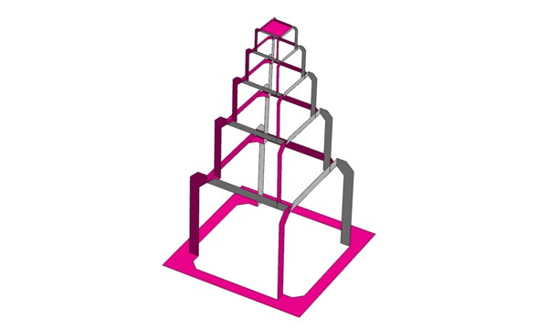 GIF
GIFMiyamoto Tower kirigami pattern designed by Yoshinobu Miyamoto. Crease pattern from Happy Folding.
 All imagesPermalink | 0 comments, 0 likes, 10,782 viewsWas this answer helpful?
 -
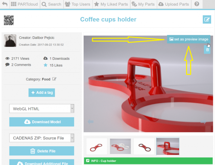
Once when you upload files and renders/photos of your 3D model on PARTcloud.net, simply go to the render/photo you would like to have as ...
Once when you upload files and renders/photos of your 3D model on PARTcloud.net, simply go to the render/photo you would like to have as a privew and click on an "Image" icon (upper right corner).
 Permalink | 0 comments, 0 likes, 6,176 views100% users marked this FAQ as helpful.|1 voteWas this answer helpful?
 -
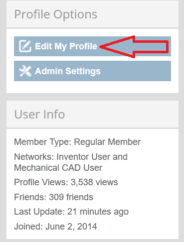
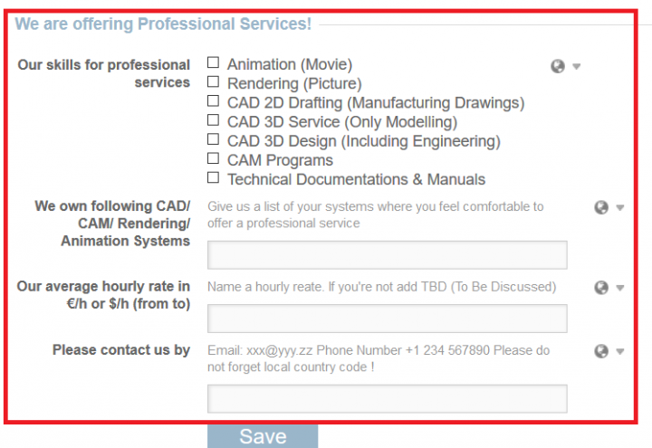
1. Go to your account/profile and click on "Edit". 2. Scroll all the way down and you will find options where you can add info...
-
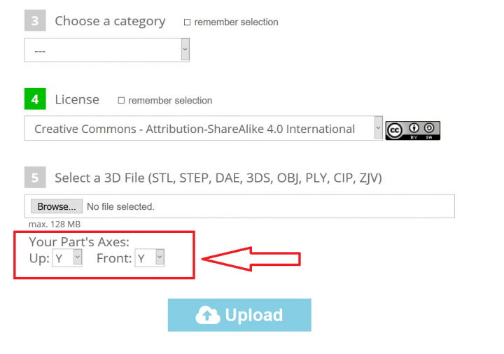
Simply choose wanted option in coordinate system while uploading your 3D model on PARTcloud.net
-
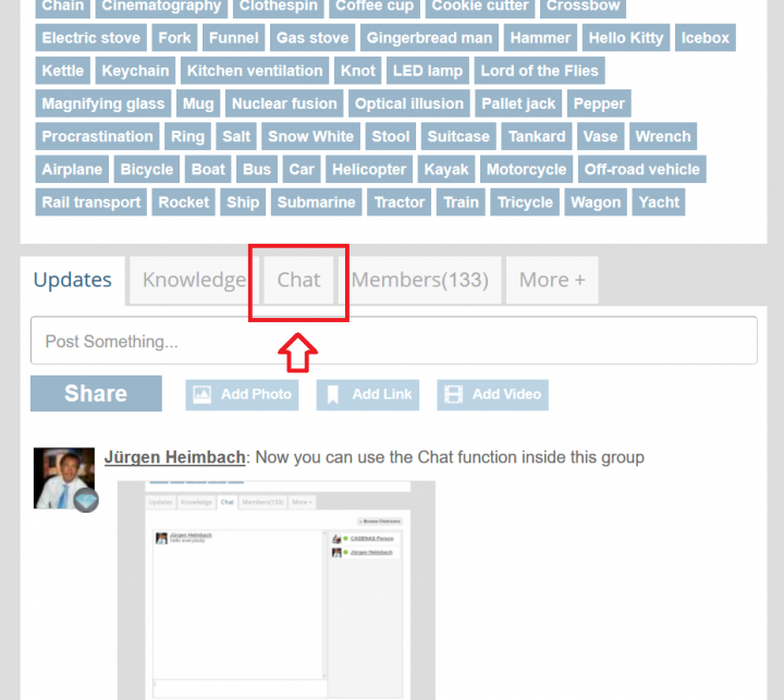
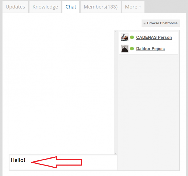
1. Go to "Weekly Challenge group" and click on "Chat" window. 2. Scroll down and you will find the place where you can write a...
-
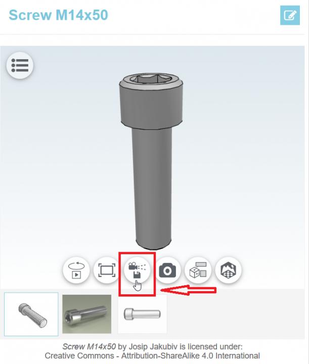
1. Go to your uploaded model on PARTcloud.net and click on 3D model. 2. Use mouse to choose size and position of 3D model. ...
1. Go to your uploaded model on PARTcloud.net and click on 3D model.
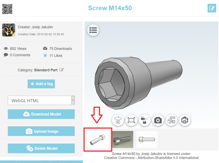
2. Use mouse to choose size and position of 3D model.
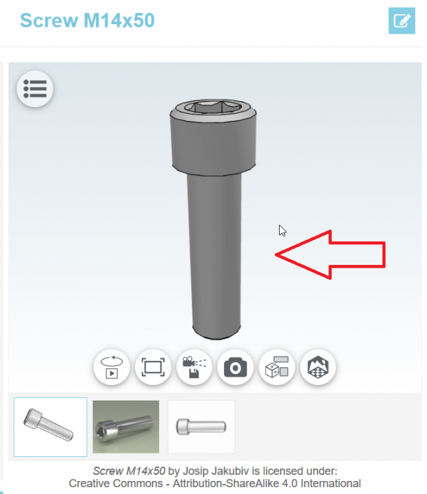
3. Lock the position by clicking on camera icon - done!
 Permalink | 0 comments, 0 likes, 5,150 views100% users marked this FAQ as helpful.|2 votesWas this answer helpful?
 -
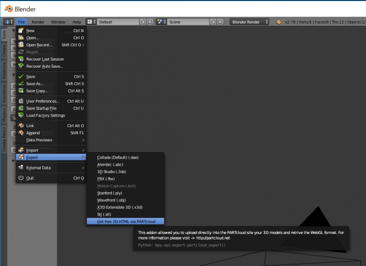
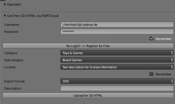
1. Download the PLUGIN (BETA) and install to BLENDER addon directory Filename: Size (KB) Expir...
-
To share its 3D models with friends or colleagues, users can use the PARTcloud.net 3D Printing & Sharing Community app. Models can be upl...
To share its 3D models with friends or colleagues, users can use the PARTcloud.net 3D Printing & Sharing Community app. Models can be uploaded via PARTcloud.net on the 3D CAD models download portal PARTcommunity in STL and STEP format.
1. Users have to login at PARTcloud.net or create an account free of charge in order to enjoy all the advantages of the Sharing Community. If you are already registered for the 3D CAD models download portal PARTcommunity, this is also valid for PARTcloud.net .
The components are uploaded and the information as well as details filled in so that the 3D CAD model can be found more easily by other users.
2. After uploading, the 3D CAD model appears in your own portfolio.
3. Now the app PARTcloud.net 3D Printing & Sharing Community by CADENAS has to be installed on the smartphone or tablet.
4. In the app itself, the search field is used to enter searched terms - in addition, the two filter functions "newest" and "select a category" can be used.
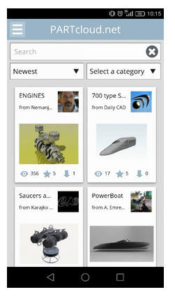
5. Once you have found the 3D model, you have a well-known features, such as downloading the model. In addition, app users have the opportunity to link model and camera function to each other. Thus, two realities can be linked for spectacular photo shots.
 Permalink | 0 comments, 0 likes, 5,724 viewsWas this answer helpful?
 -
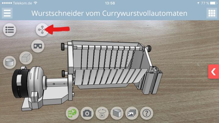
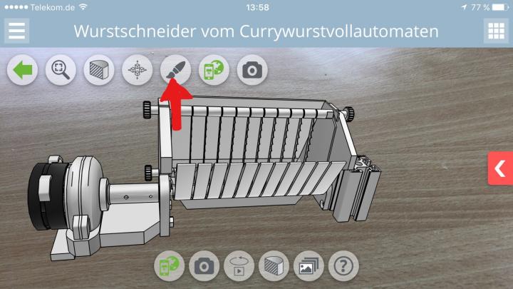
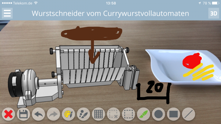
1. Download the APP 2. Activate the SKETCHER 3. use the SKETCHER
-
1. Go to PARTcommunity.com homepage and click on "Add Video" 2. Click on "Choose Source" 3. Choose between YouTube or...
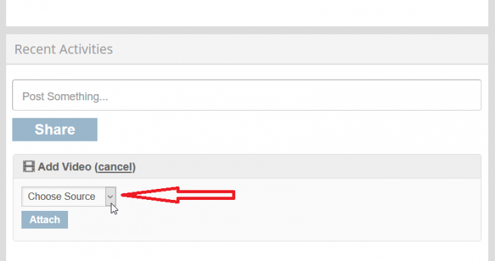
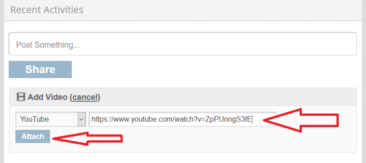
1. Go to PARTcommunity.com homepage and click on "Add Video"
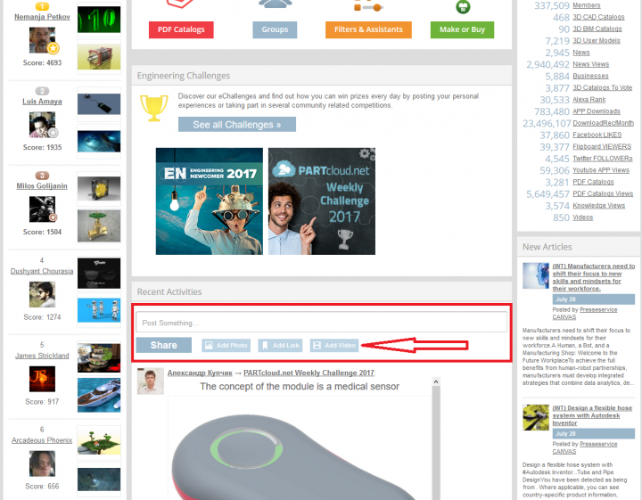
2. Click on "Choose Source"
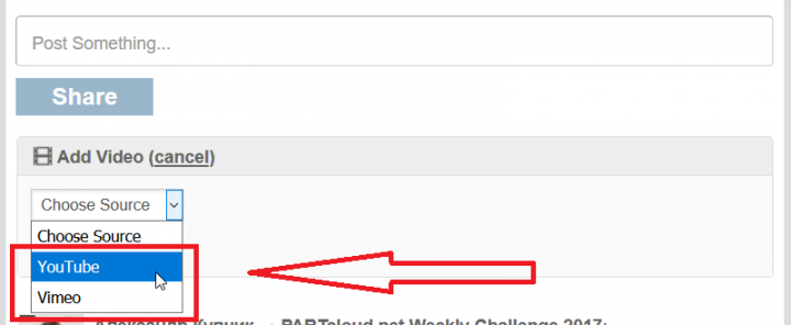
3. Choose between YouTube or Vimeo (depending on the source of the video clip you would like to publish). You cannot publish video clip from your computer, only between this two options.
4. Go to the video clip and copy the link
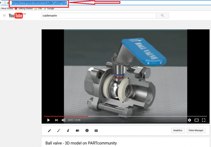
5. Paste the link and click on "Attach"
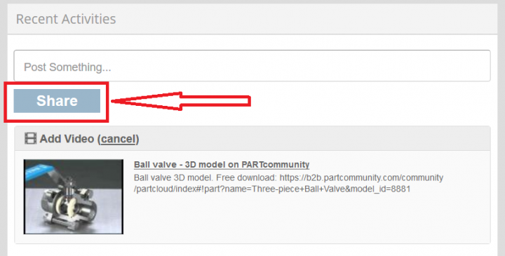
6. When the video clip is uploaded, click on "Share"
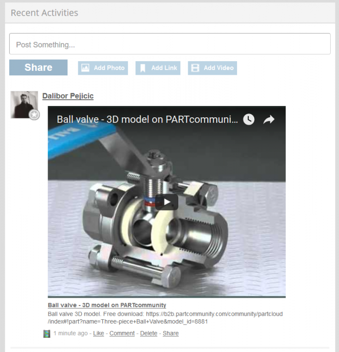
7. Your video clip should be published now. Simply click on it to watch it.
 Permalink | 0 comments, 0 likes, 2,711 views0% users marked this FAQ as helpful.|1 voteWas this answer helpful?