Manual
Login
Our 3D CAD supplier models have been moved to 3Dfindit.com, the new visual search engine for 3D CAD, CAE & BIM models.
You can log in there with your existing account of this site.
The content remains free of charge.

Top Links
Manual
 |
The Connection section is subdivided in:
![[Note]](/community/externals/manuals/%24%7Bb2b:MANUALPATH/images/note.png) |
Note |
|---|---|
|
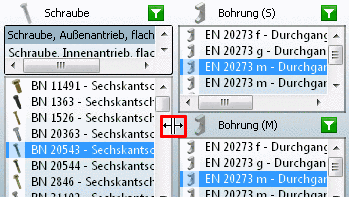
You can adjust the section size of the single bolting elements via grip. The grip is visible, when you move the mouse over the border line between two sections.
| |
The single points are described in the next chapters in detail.


In the following the single buttons are described:
-
Restores the original state in the Connection section and removes all selections.
-
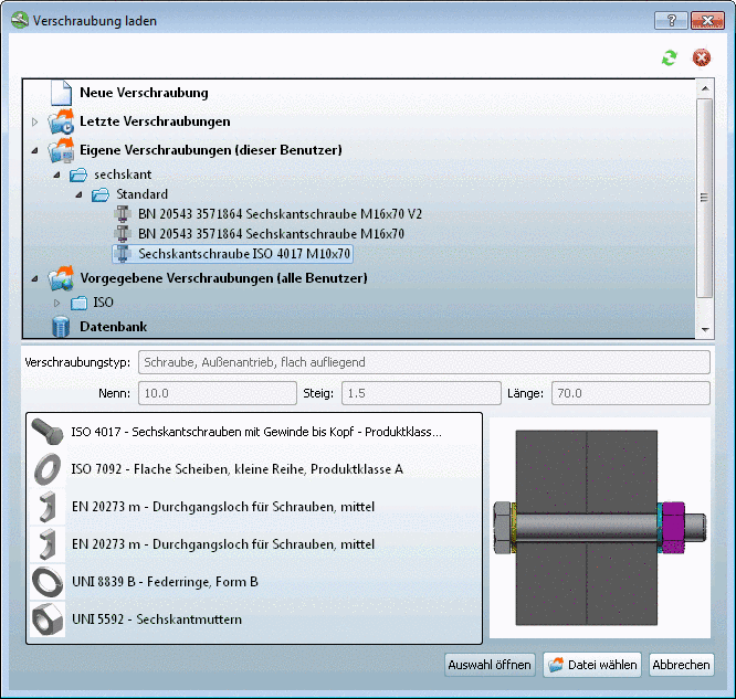
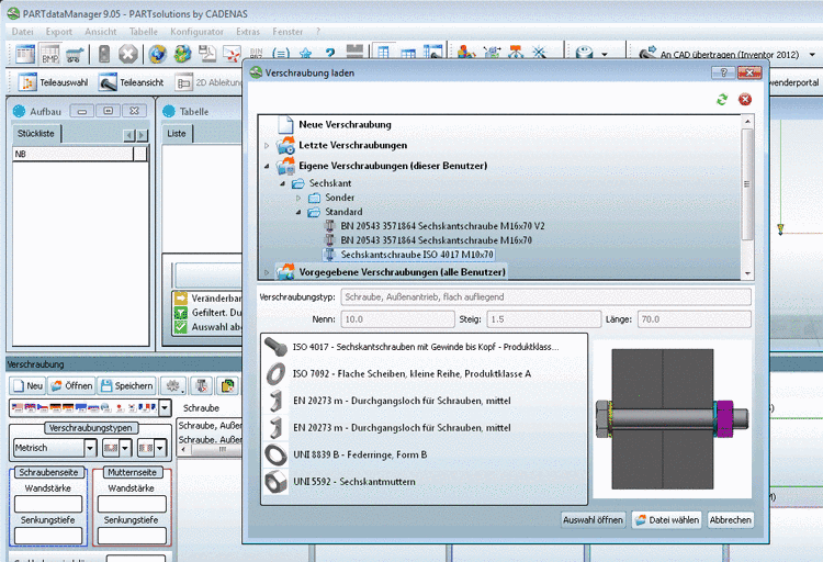
The Load bolted connection dialog box is opened.
In the upper section the following options are available:
-
Via double-click the window is closed and you can create a new connection.
-
Own bolted connections (this user):
If you have already saved own connections, then these are displayed here (see next point).
-
Predetermined bolted connections (all users):
If some connections have been already preset, then these are displayed here.
-
Note Only when ERP integration is available (see Section 3.1.1.10.5.1, “Create and edit ERP connections ”).
-> Afterwards in the lower section a preview image and the respective components are displayed.[63]
The dialog box contains the following buttons:
-
With click on a buttons the Load configuration dialog box opens. Browse to the desired file and load it via .
-
In this way you make sure that you get the current view.
Database entries[64] are not automatically updated. For this purpose use the button.
-
-
Save connections which are frequently needed. Via button
 (see above) you can load it
anytime.
(see above) you can load it
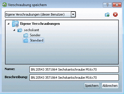
anytime.The Save bolted connection dialog box opens.
In the upper list field select one of the following options:
-
Own bolted connections (this user)
Save your own connections here. Then these are later available to you.
-
Predetermined bolted connections (all users)
Connections saved here are available to all users.
Shouldn't you have writing permission for this option, then you will receive a respective error message.
If needed create a hierarchical structure:
In order to remove directories or connections proceed as follows:
-
-
Configure extended settings with this menu.
-
Here you can configure the startup mode of the
 Connection
section.
Connection
section.The following options are available:
-
The Connection section opens with the lastly loaded connection.
-
The Connection section opens with an empty connection. All filters are removed. This corresponds to the state after click on the
 button.
 -
Bolted connection selection window
This is the preset option. You can change the selection anytime.
The Connection sections still remains empty and the Load bolted connection dialog box is opened in the foreground.
Select a connection from one of the categories or double-click the
New bolted connection button in
order to start with an empty connection. -
Determine a concrete connection which is basically loaded when the dialog box opens. Hereto proceed as follows:
Now whenever the dialog box is opened the chosen preferred connection is loaded. If you want to configure another connection, then simply click on
.
-
-
This setting concerns the connection components washer, lock washer and nut.
-
-
This option determines if the holes are exported as actual parts.
Note Whether the appropriate holes (through hole/blind hole) are also created depends on the CAD system (on this see Section 2.5, “CAD specific menu commands ”).
-

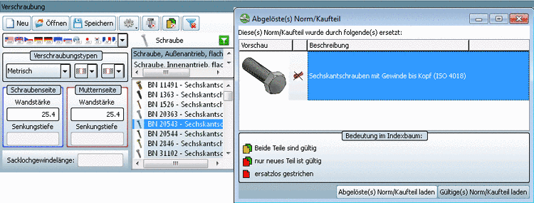
 Dialog Obsolete standard part/manufacturer part on/off
The same icon is also displayed in the index tree, if there is both an obsolete and a valid standard part/supplier part available. On this compare Section 3.1.1.12.3.3, “ Obsolete standard part/manufacturer part ”.
-
Saves the time to separately click on each single filter in the component and value range section.


|
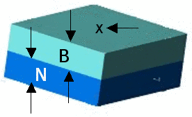
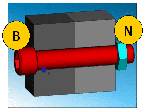
Part thickness and Counterbore depth: In the field Part thickness (B) or Part thickness (N) (see adjoining figure) the respective part thickness of the bolting components is displayed. These thicknesses correspond to the Distance of the chosen Layers, Edges and Points in the CAD system. Detailed information on this is found under Section 3.1.1.10.3, “Small example from A to Z”. Only at connections which contain counterbores, the respective fields Counterbore depth (S) or (M) are active. If the connection type Blind hole is selected, in addition the determination of Blind hole thread length is possible. |
|

The input fields for the hole length (Part thickness), Blind hole thread length and Counterbore depth signalize the validity of the inserted value by color code:[65]
Green: Value is supported by the current hole or the other selectable holes.
Yellow: There is a risk, that the current value is not supported by a valid hole. But this can only be checked when the settings are performed. Another message is: There is a connection available which supports this value, however this can be in another connection type, e.g. for a connection with another base unit.
Red: Value is not supported by any hole under no circumstances.
Note: The input of a counterbore depth > hole length is prevented.
|
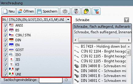
In the Catalog selection list field the installed standard catalogs are displayed. Check the catalogs which you want to involve for the connection selection. |
|
|
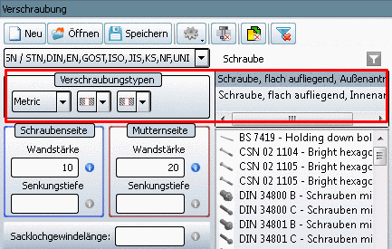
Before you can select individual components and values, you have to perform basic settings concerning Measure unit, Hole type and counterbore type. |
|


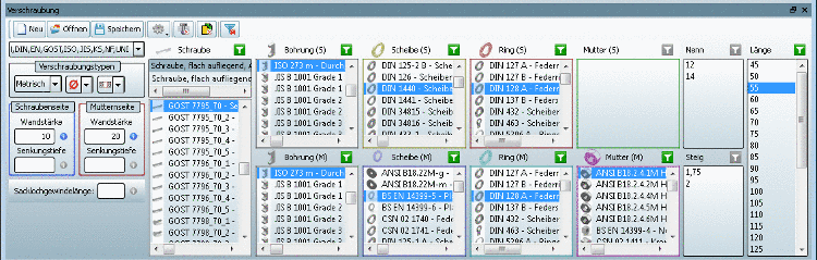
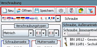
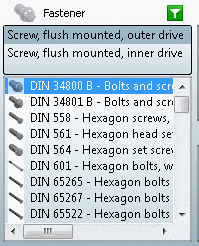
When all statements concerning connection type are done, the resulting available types of fasteners are displayed in the Fastener section above the single bolt standards. Compare Fig. „Screw types“.
In the list click on the desired Type of bolt.
The following types can be displayed for example depending on the installed and activated catalogs:

-
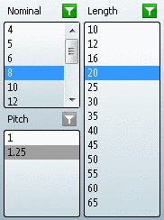
The field Nominal shows the possible Nominal diameter of the connection.
PARTdataManager always calculated the intersection from a comparison of all available connection elements. Then the sizes of this intersection are displayed in the field Nominal. Example: If there is a bolt with the variants M1 to M5 and a nut with the variants M4 to M8, then the possible nominal diameters M4 to M5 result.
-
Possible Nominal length according to the respective bolt. For each nominal diameter of a bolt a certain selection of lengths is assigned.
-
The possible pitches for the respective selected bolt and nut standards are displayed in the field Pitch.
|
Note |
|---|---|
|
Each change of a connection component or a value results in a new calculation of all components and values and in an update of 3D view and Table. Meaning, if the bolt size is changed from M4 to M6 (variable "Nenn") for example, the selection of nuts is adjusted to this size. Furthermore the possible values for length and pitch are also adjusted. | |