Manual
Login
Our 3D CAD supplier models have been moved to 3Dfindit.com, the new visual search engine for 3D CAD, CAE & BIM models.
You can log in there with your existing account of this site.
The content remains free of charge.

Top Links
Manual
 |
The single parts created in PARTdesigner can be assembled with the Configurator.[94]To enable this, in PARTdesigner, the parts must be assigned precisely defined and named insertion and connection points.
A cuboid contains a boring into which a screw is to be inserted later (assembly configuration). Therefore a connection point needs to be applied for the boring.
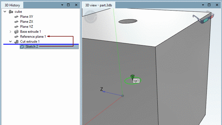
Click on the Face, in which the boring is to be applied. --> The according Sketch shows up in the History highlighted in color.
-
Right-click on the context menu of the sketch (in this example, Sketch 2).
-
"Catch" the center of the circle (boring) with your cursor and affix it with a simple mouse-click.
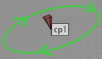
--> The point gets a green triangle symbol .
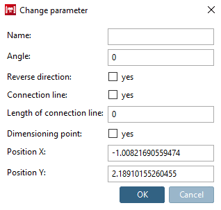
--> The Change parameter window opens.
When freely placing the insertion point (without snap), then in the dialog the options Position X and Position Y are found in addition.
Assign a name to the connection point - for example: cp1 - and confirm with .
Optionally, you may make changes in the other fields as well.
-
Angle: Rotation of insertion point
![[Note]](/community/externals/manuals/%24%7Bb2b:MANUALPATH/images/note.png)
Note The connection point is rotated around its pyramid top. An example on this can be found under "Beispiel "Hebelposition".
If rotation is required in another plane, please use respective reference planes, in order to place the connection point.
Another use case can be found under Section 7.9.3.2.1.4, “ Connection points at miters ”.
Reverse direction: Inversion of direction is needed at a hinge, for example. The hinges should fit contra-rotating.
Connection line and Length of connection line: Connection lines can be used for movable elements. For example, for connectors of profiles, which move in a notch. See Section 7.9.3.2.1.6, “Create Connection line ”.
Dimensioning point: Activate the option, if a connection point shall be used as dimensioning point as well. See Section 5.10, “Specify automatically created dimensionings (notations) for 3D view and 2D derivation ”.
Also see Section 7.9.3.2.1.3, “Direction of connection points ” und ???.
-
-
Click on the button Accept changes
 .
.--> In the 3D view the connection point is also identified with a green pyramid symbol .


By default, the coordinate system is not shown at connection points.
However, you can it enable by setting the key value to "1" (under $CADENAS_USER).
[Settings3DPane]
cpCoordinateSystem=1

