Manual
Login
Our 3D CAD supplier models have been moved to 3Dfindit.com, the new visual search engine for 3D CAD, CAE & BIM models.
You can log in there with your existing account of this site.
The content remains free of charge.

Top Links
Manual
 |
The name conventions is to be explained in detail using the example of a profile:
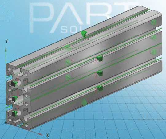
A connection point is needed in the center of the section and one in each hole. Compare Fig. „3 connection points each at start and end, 8 insertion lines at the ducts“.
The connection point in the center of the section is called start, the others are listed as start_a, start_b etc.
The same counts for the profile end.


Sideway connection points (insertion lines)
![[Note]](/community/externals/manuals/%24%7Bb2b:MANUALPATH/images/note.png) |
Note |
|---|---|
|
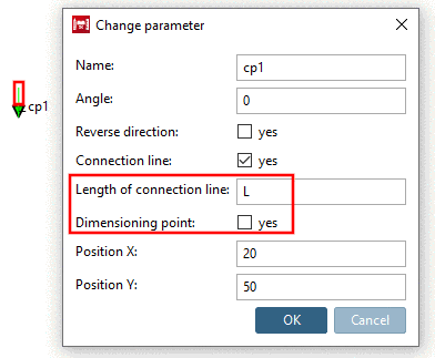
The sideways Connection points are created as Connection line. See Section 7.9.3.2.1.6, “Create Connection line ”.
| |
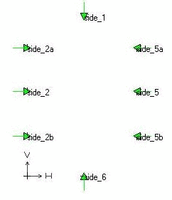
The following image is an example of the name convention for the insertion lines on the side. Your basic sketch is located on the start plane of the profile.
![[Important]](/community/externals/manuals/%24%7Bb2b:MANUALPATH/images/important.png)


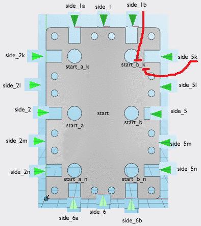
Example of a complex name convention with many connection points and insertion lines and different proportions
The start/end connection points/insertion lines are now a letter combination of top/side and or bottom/side: