Manual
Login
Our 3D CAD supplier models have been moved to 3Dfindit.com, the new visual search engine for 3D CAD, CAE & BIM models.
You can log in there with your existing account of this site.
The content remains free of charge.

Top Links
Manual
 |
Since the concept described above has its origin in eCl@ss Advanced, here, the relations shall be clarified once again by using the same part. The scope is especially on connection definitions in the eCl@ss Advanced format.
The following figure shows the connection definition in eCl@ss Advanced.
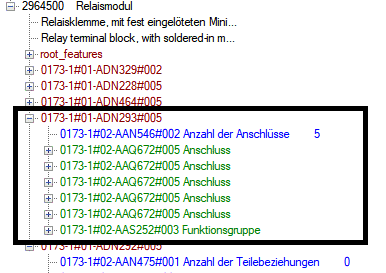
The device has 5 connections (Anschlüsse) and 1 function group (Funktionsgruppe) (compare above figure). The function group is the container for the part's electrical functionality and has 2 functions in the given example.
According to this division 3D data and other properties of connections are defined in the sections AAQ672 (="Connection").
Information on connection logic, etc. are determined by the functions in the function group.
![[Note]](/community/externals/manuals/%24%7Bb2b:MANUALPATH/images/note.png) |
Note |
|---|---|
Physical and logical connection properties are separated. This strict separation is not so strong in the CNS classification system. | |
The most important information of a representative connection for part 2964500 is shown in the next figure. Under AAQ672, beside 3D coordinates with connection direction (see framed data), normally information on conductor material, cross section, its color and stripping lengths, etc. is found. (In this case, classifying is "sparingly" used without this additional information.)
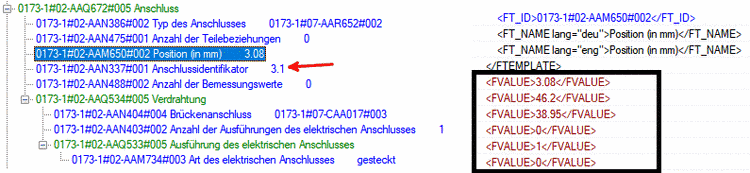
Properties of connection: The key AAM650 defines connection position and direction according to ISO AXIS ID data type definition. The relation to logical connection properties is realized by connection identifier AAN337 (here ID = 3:1).
The connection identifier links physical and logical connection properties.[56]
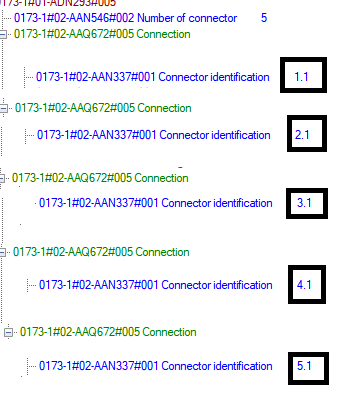
Connection identifiers of the five connections. All other data is hidden. (Above figure is representative for the other connection details omitted here).
In this case the five connections are divided in two functions (see "Number of functions 2"):
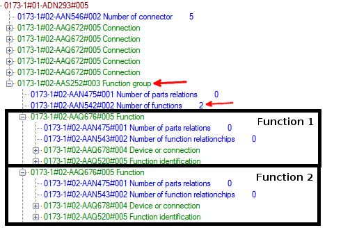
Function group with two functions (expanded on first level). Note: eCl@ss is largely independent of languages (English and German function is both described by "AAQ676")
The relation between connection and function takes place within eCl@ss key AAQ678. Two connections belong to the first function and three connections to the second function. As an example we consider the respective function entry of Identifier "3:1".
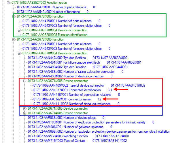
Function group with two functions. Two connections (within AAQ678; not displayed here) belong to the first function (green frame). The second function contains three connections (red and blue box). The entries of identifier "3:1" are expanded in the red box. Note the large amount of date, which serves the "bookkeeping" to a great extent.
The considerations can be summarized as follows: (The function number can indirectly be seen in above figure.)
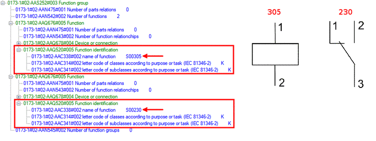
Now that the logical connections are linked with the physical, the question arises how the respective circuit symbol of the entire device looks like (a device with one function group and two functions). This happens within eCl@ss Keys AAQ520.
The part is described by a combination of S00305 (="coil") and S00230 (=switch).
In summary:
On the side of the CNS classification the attribute Connection EclassSymbolMap shows a quite compact formulation of the described concept.
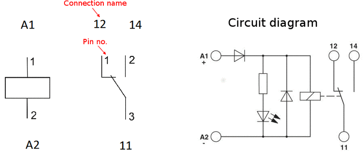
Following figure shows the comparison of the logic from the table with the circuit from the datasheet.