Manual
Login
Our 3D CAD supplier models have been moved to 3Dfindit.com, the new visual search engine for 3D CAD, CAE & BIM models.
You can log in there with your existing account of this site.
The content remains free of charge.

Top Links
Manual
 |
In this chapter, we have a look on how to create general symbols (circuit symbols), which are specified by the eClass symbol representation (AAS425).
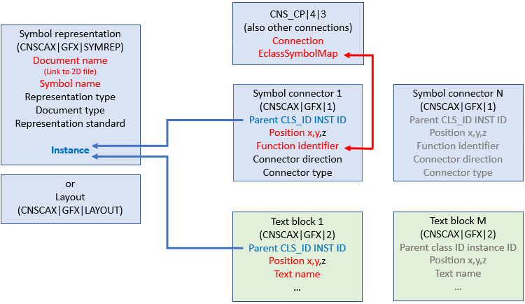
Above diagram shows a fully differentiated symbol representation where especially 2D symbol connectors are connected with 3D connectors. This situation can be modified in any way by replacing the electrical connections CNS_CP|4|3, for example, by the classification representing hydraulic connections.
When creating the symbol representation the task now is to achieve different links.
Central hub is the class CNSCAX|GFX|1 (Symbol connector).
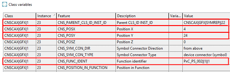
The symbol connector, class CNSCAX|GFX|1, includes ...
... in the attributes CNS_POSX and CNS_POSY, the X/Y coordinates for placing the pin on the symbol representation,
... in the attribute Parent CLS_ID INST_ID, the reference to the class CNSCAX|GFX|SYMREP, which in turn provides the link to the corresponding 2D symbol representation,
... in the attribute Function identifier, the reference to the corresponding physical connection (CNS_CP|4|3).
Both layout and symbol representation describe abstractions of the physical 3D model. They differ both in regard to the level of abstraction and in regard to the focus conceptually. When layouts focus on the geometrical 2D representation of the physical model, symbol representations focus on the logical functionality of the model. Both concepts are not interchangeable.
Layout: According to ISO 5455:1979 layouts have the characteristic of a scale in particular, meaning the scaling factor between 2D representation and 3D model. This particularly means that for layouts sizes such as height and width can be defined, which are directly related to the 3D model.
Symbol representation: The symbol representation as logical description of a part's functionally is a deeper abstraction of the physical model, where all properties like height, width and depth, if referring to the 3D model, are being omitted. Only the circuit symbol is represented.
We can clarify the difference with the help of two transformers: The one feeds a power line, the other serves to charge the mobile phone. The layout display is very different, if the scaling factor is unchanged, which mirrors the different physical dimensions of the two transformers. In both cases the symbol representation could be the same. In the CNS classification, layouts are described by the class CNSCAX|GFX|LAYOUT and (logical) symbol representations by the class CNSCAX|GFX|SYMREP.
-
N functions -> N symbols with N DXFs (standard case)
In the example under Section 5.13.10.3.1.1, “Symbol representation with Phoenix Contact 2903156” there is ONE function with ONE corresponding symbol representation (CNSCAX|GFX|SYMREP) with 8 symbol connectors (CNSCAX|GFX|1). All pins of the function refer to this ONE representation.
-
Currently this functionality is not yet available. An example can be found under Section 5.13.10.4.2, “Connections, Functions, IEC symbols”.
-
Classification of a symbol representation in the sense of below example under Section 5.13.10.3.1.1, “Symbol representation with Phoenix Contact 2903156” can only be created as "Addon", if the part has already been completely classified following the main steps of the electrical classification. In particular this means the creation of classes and attributes as described under Section 5.13.10.4.2, “Connections, Functions, IEC symbols” .
Working symbols (Section 5.13.10.4.2, “Connections, Functions, IEC symbols”) are precondition (can be omitted for pipeline import and only applies for manual or semi-automatic classifying[54]).
Used classes for symbol representation "advanced" are CNSCAX|GFX|SYMREP [symbol representation(s)], CNSCAX|GFX|1 [symbol connections] and CNSCAX|GFX|2 [text blocks].
-
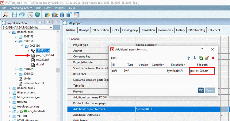
The symbols (2D vector graphic files (DXF/DWG/2db) have to be integrated in PARTproject under Additional export formats (at any place in the catalog).
-
![[Note]](/community/externals/manuals/%24%7Bb2b:MANUALPATH/images/note.png)
Note Exactly this ID has to be entered in class CNSCAX|GFX|SYMREP, attribute CNS_DOC_CNSURI. See below.
In the list field, under Type, select the appropriate format.
Enter a description. It will be displayed under Additional export formats.
-
[54] At this the possibility of a symbol library is offered so that the following steps have only be done once when creating the library. Then equipping a part with symbols only means applying a template basically, which already contains the described symbol classification.
