Manual
Login
Our 3D CAD supplier models have been moved to 3Dfindit.com, the new visual search engine for 3D CAD, CAE & BIM models.
You can log in there with your existing account of this site.
The content remains free of charge.

Top Links
Manual
 |
These examples give an overview on all important steps.
Detailed information on the individual steps can be found when you follow the links.
This example shows
how to find a part via Full-text search,
afterwards how to specify via  Part view and finally
how to export it into the CAD system.
Part view and finally
how to export it into the CAD system.
-
Open the PARTdataManager from the PARTsolutions menu of your CAD system with the command Insert 3D or for 2D CAD systems with Insert 2D.
More information about the CAD interfaces can be found under Chapter 2, Open PARTsolutions from CAD systems.
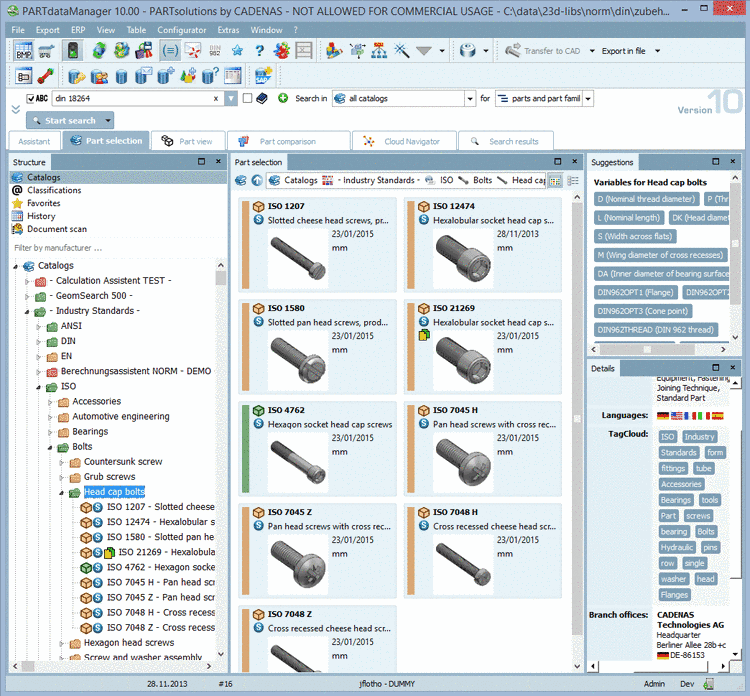
The following image shows the starting user interface of PARTdataManager.[19]
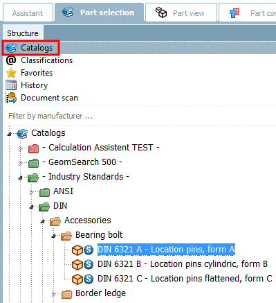
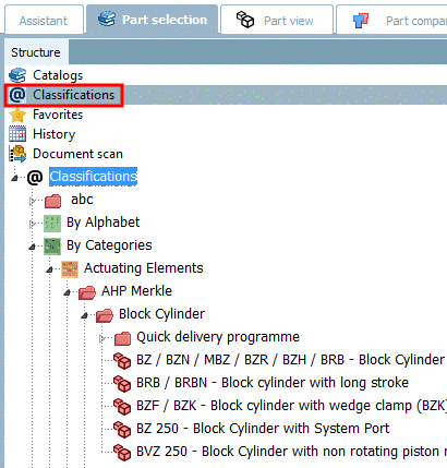
Basically you can search for the desired part via index trees (e.g. Catalogs or Classes) whereon we do not focus in this example.
In the example in hand we will perform a Full-text search. This is opened and activated at program start by default.
Detailed information on all search methods is found under Section 3.1.1.6.4, “ Search methods ”.
-
Leave the presettings Search in all catalogs for parts and part families.
You can find detailed information on this under Section 3.1.1.6.2, “Determine catalog/classification/directory to be searched” and Section 3.1.1.6.3, “ Search for Parts | Part families and Parts ”.
-
Set the following entry in the input field:
Cardan joint
You can find detailed information on this under Section 3.1.1.6.4.2, “ Full-text search ” or directly in the user interface with click on
 .
. -
-> The search results are listed below on the tabbed page Search results.
You can realize that you already reached the project level (deepest level of the index tree structure) at the respective icons (e.g.
 (part) or
  (assembly)[20].
 -
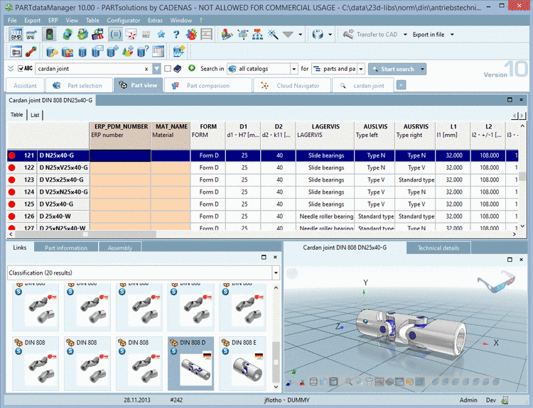
Perform a double-click on the desired part.
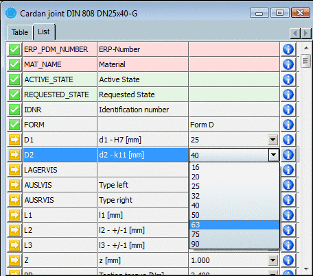
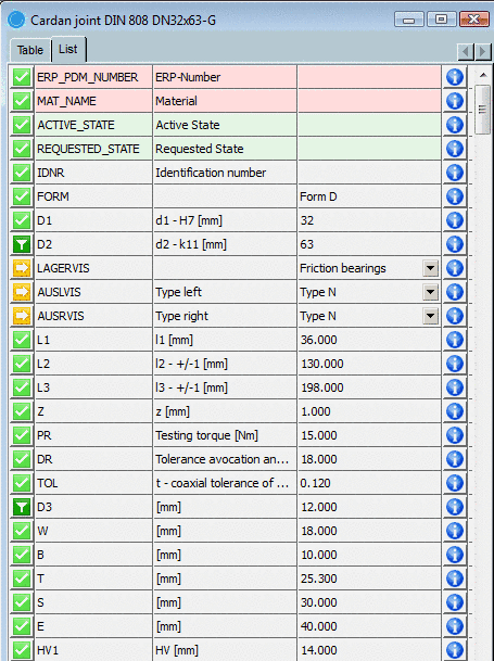
On the tabbed page Part view now determine the characteristic of the part.
The following figure shows the setting options of the Part view:
The default values, when opening the Part view [21] page, refer to a middle table row.
-
All table values are listed one beneath the other.
The following symbols clarify the selection options:
Meaning 

Several values available in list field / Changeable value:
When you select a value in the list field, then automatically depending variables are changed as well.
The following two possibilities can occur:
-
At a depending variable only one value is still possible. Then the variable is marked with
 .
.In the opened list field you see a black value (the set and the others in blue font color.
-
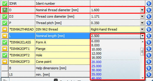
There are restrictions at a depending variable, but still several values are possible.
Then the variable is marked with
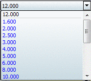
further on.In the opened list field you see black values. These are not affected by the current selection.
Furthermore you see blue values. These have been filtered by the current selection.
Example: D has been set to the value 1.6. Thereby at L values greater than 20 are not possible anymore. These now are displayed in blue font color.
-
by filtering another variable, the selection was restricted to one single value.
-
by filtering another variable, the selection was restricted to one single value.
![[Note]](/community/externals/manuals/%24%7Bb2b:MANUALPATH/images/note.png)
Note This does not mean that you cannot perform changes anymore.
However by the selection of a blue value all restrictions performed before are removed.

The value has been pinned by clicking on
or or by direct selection.-
Actively filtered variable (by selection in the list field or by clicking on the symbol)
In the related list field all values are blue, except the set one. This is black.
-
Filtered variables restrict depending variables. There values, not available anymore, are also colored in blue.
Variables unaffected by the filtering are still displayed in black.
Compare Fig. „Example: D has been set to the value 1.6. Thereby at L values greater than 20 are not possible anymore. These now are displayed in blue font color.“.
Yellow and orange variables (value range fields) can not be filtered. (These are set via
 .)
.)
By clicking on this symbol the Enter value window opens. For value ranges (yellow and orange fields) you may make a selection here.
In the example at hand D2 is given the value 63.
The symbol automatically changes from
to . -> Thus the value is filtered (fixed). At
some depending lines (variables) [Z, PR, DR, TOL] with only one possible
value the green checkmark appears. -
-
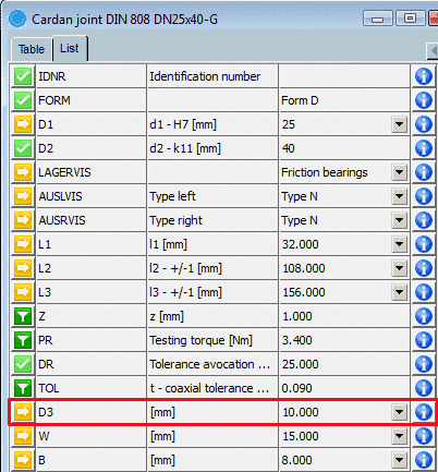
Now variable D3 receives the value 14.
-> Almost all variables are now set.
Afterwards, you should test if the settings are correct for still changeable values
.You can find detailed information on list view under Section 3.1.1.7.1.2, “Determine characteristic in list view ”. See also Section 3.1.1.7.1.1, “ Determine characteristic in table view ”.
-
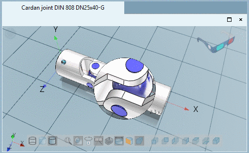
In the 3D view you can view and test the part three dimensionally.
For this you have many additional functions.[22] [23]
In order to inspect details you have the magnifying glass function available.
-
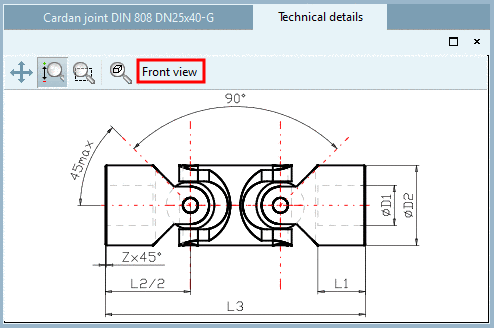
The tabbed page Technical details shows Dimensioning views (e.g. Front view, Side view) and Display mode.
If there are selection options select the desired one in the list field.
For Assemblies yon can see the bill of material under tabbed page Assembly -> tabbed page Bill of material. The number of single parts is shown under Amount.
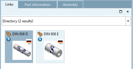
On the Links docking parts similar in construction are shown.
-
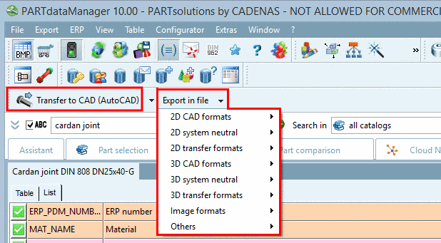
If you are happy with your selection you can export the part or assembly to your CAD system.
Click on the icon Transfer to CAD .[24]
Note The icon remains active regardless of whether you keep opening from the PARTsolutions menu or whether you switch directly to the PARTdataManager.[25]
Via Export in file you can also export the part onto your hard drive in various formats.[26]
-
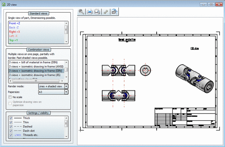
Should you want to export the part to a 2D CAD system, you must first create a 2D derivation.
-> The 2D view window shows up.
Select a view. Here in the example Frame DIN (BOM) is chosen.[27]
Now export the part as described in the last point.
Note When using a 2D CAD and clicking on the button
 Transfer to CAD, without
having created a 2D derivation, a default derivation is
transferred to the CAD system.
Transfer to CAD, without
having created a 2D derivation, a default derivation is
transferred to the CAD system.Information on setting options is found under Section 3.3.9, “"Export to CAD" tabbed page ”.


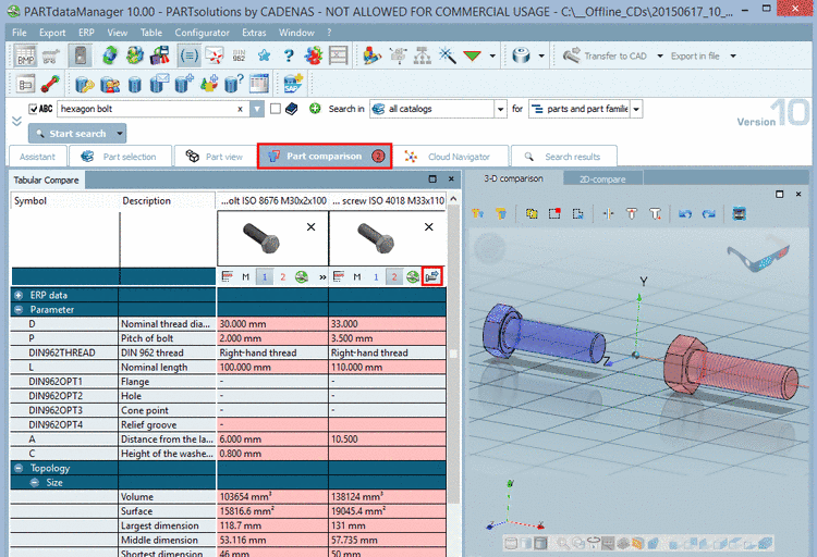
In the following it shall be explained how a search can directly deliver the desired characteristics, how these can be checked textually (table variables, topological and class attributes) and geometrically in the 3D view in the docked window Part comparison and how the desired part can be directly exported into the CAD system.
-
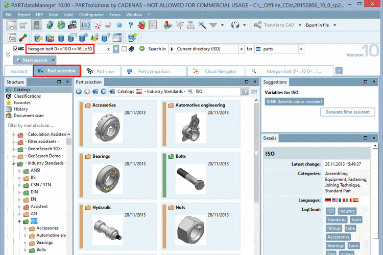
We will perform a Full-text search with the following settings:
Current selection (ISO) [select -> "Industrial Standards" -> "ISO" at the Catalogs tabbed page]
-
Full-text search with the following term:
hexagon bolt D>=10 D<=16 L=50
You can find detailed information on syntax under Section 3.1.1.6.4.2, “ Full-text search ” or inside the application with click on
.
-
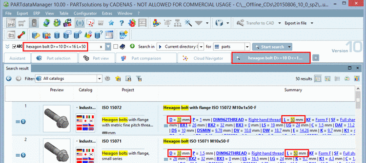
-> The view changes to the Search results tabbed page. In the result list you can find concrete single parts, which meet the condition. The respective icon signalizes that single parts are displayed
 .
.Due to the variable specification in the search results list only correct characteristics are displayed.
In the Summary column the variables are displayed. You see, that only characteristics are displayed, which meet the condition in the full-text search input field.
Also see Section 3.1.1.6.7, “ Search results ”.
-
Two hits shall be loaded into the Part comparison now:
For the first hit to be loaded click on the icon Load as first part
 and for the second one click on the icon
Load as second part
and for the second one click on the icon
Load as second part  .
.-> The docking window Part comparison is opened. The number of opened parts is shown on the tab.
Here you can check the loaded parts in many respects. Detailed information on this can be found under Section 3.1.1.6.10, “ Part comparison ”.
-
At the desired part, click on the icon Export to CAD
 .
.-> The desired part is transferred into the CAD system via interface.
Detailed information on this is found under Section 2.6.2, “ Insert 3D from the Standard and supplier parts library ”.
[19] If the assistant window should show up, open the part selection via the corresponding button in the "Views" toolbar or click on "Part selection" in the assistant window. If you activate "Save selection" in the assistant window, the assistant window will no longer show up during the start, however it can be opened via the question mark symbol in the toolbar at any time.
[20] These are only the most frequently used icons. All other you can find under Section 3.1.1.12, “Legend: Used icons on catalog, directory, project level and part view ”.
[21] If the
search has been performed with the Single parts option, the values are according to the
opened characteristic.
[22] More detailed information concerning the 3D preview can be found under Section 3.1.1.7.5, “ "3D preview" window ”.
[23] More information about the 3D context menu can be found under Section 3.1.3.3.2.3, “Context menus: 3D / 2D / Technical specifications”.
[24] Information about all CAD integrations can be found under Chapter 2, Open PARTsolutions from CAD systems.
[25] If a "valid" model is opened in the CAD system, the icon is automatically active in the PARTdataManager.
[26] Detailed information about export formats can be found under Section 3.1.2.1.2, “ Export to CAD systems without PARTsolutions interface - Export in file ”.
[27] You can find detailed information on this under Section 3.1.1.11.3, “ Create 2D derivation ”.
