Manual
Login
Our 3D CAD supplier models have been moved to 3Dfindit.com, the new visual search engine for 3D CAD, CAE & BIM models.
You can log in there with your existing account of this site.
The content remains free of charge.

Top Links
Manual
 |
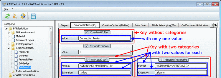
All setting options are based upon configuration files. These are structured by blocks and keys. Keys can contain categories which represent a condition depending on which the key is used or not. Keys contain one or more values.
The following figure shows how the particular blocks, keys, categories and values are displayed under PARTadmin -> Category -> PARTsolutions -> CAD integration.
-
Under Category -> CAD integration blocks are represented via tabbed pages and are selected via tabs.
The following list shows cad encompassing all kinds of tabbed pages. These may have different names depending on CAD system.
-
On the Simple tabbed page the most important settings are found.[32]
-
Attribute settings(3D/2D/native)
Each CAD system has several tabbed pages for the attribute mapping.
-
-
Each tabbed page lists the keys one below the other.
In the figure above "ConnPointFolder", "ExcludeFromBom", etc.
If there are different categories inside a key (information regarding creation of categories is found under Section 2.2.1.2, “ What are categories?”), then these are displayed side by side (see figure above FileName(Part) and FileName(Assembly)).
The checkbox
 before each single key name controls
activation and deactivation.
before each single key name controls
activation and deactivation. -
If a key contains several values, then these are displayed one below the other inside the key block (see figure above).
<GENNAME><MATERIAL(_)>
.sldprt
.sldasm
![[Note]](/community/externals/manuals/%24%7Bb2b:MANUALPATH/images/note.png)
[32] Here especially the default settings from V8.1 are found. More complex settings or new ones with V9 are found on the other tabbed pages.
