Manual
Login
Our 3D CAD supplier models have been moved to 3Dfindit.com, the new visual search engine for 3D CAD, CAE & BIM models.
You can log in there with your existing account of this site.
The content remains free of charge.

Top Links
Manual
 |
![[Note]](/community/externals/manuals/%24%7Bb2b:MANUALPATH/images/note.png)
In the
configuration file ifacad.cfg, in the block
[CreationOptions],
under Layer
configuration, you can find the following blocks:
-
;Thick Solid Lines AcadLayerName_00=AM_0 AcadLayerLineType_00=Continuous AcadLayerLineColor_00=7 AcadLayerLineWeight_00=50 AcadLayerVisibility_00=1 -
;Thin Solid Lines AcadLayerName_01=AM_2 AcadLayerLineType_01=Continuous AcadLayerLineColor_01=5 AcadLayerLineWeight_01=50 AcadLayerVisibility_01=1 -
;Hidden Lines AcadLayerName_02=AM_3 AcadLayerLineType_02=ACAD_ISO02W100 AcadLayerLineColor_02=6 AcadLayerLineWeight_02=25 AcadLayerVisibility_02=1 -
;Thin Center Lines AcadLayerName_03=AM_7 AcadLayerLineType_03=MITTE AcadLayerLineColor_03=4 AcadLayerLineWeight_03=25 AcadLayerVisibility_03=1 -
;Thick Center Lines AcadLayerName_04=AM_10 AcadLayerLineType_04=MITTE AcadLayerLineColor_04=4 AcadLayerLineWeight_04=50 AcadLayerVisibility_04=1 -
;Visible Attributes AcadLayerName_05=AM_6 AcadLayerLineType_05=Continuous AcadLayerLineColor_05=2 AcadLayerLineWeight_05=35 AcadLayerVisibility_05=1 -
;Hidden Attributes AcadLayerName_06=CNS_HIDDEN_ATTRIBUTES AcadLayerLineType_06=Continuous AcadLayerLineColor_06=2 AcadLayerLineWeight_06=35 AcadLayerVisibility_06=0 -
;Visible Threads AcadLayerName_07=AM_5 AcadLayerLineType_07=Continuous AcadLayerLineColor_07=3 AcadLayerLineWeight_07=25 AcadLayerVisibility_07=1 -
;Invisible Threads AcadLayerName_08=CNS_HIDDEN_COSMETICS AcadLayerLineType_08=Continuous AcadLayerLineColor_08=3 AcadLayerLineWeight_08=25 AcadLayerVisibility_08=0 -
;Hatches AcadLayerName_09=AM_11 AcadLayerLineType_09=Continuous AcadLayerLineColor_09=3 AcadLayerLineWeight_09=25 AcadLayerVisibility_09=1 -
;Connection Points AcadLayerName_10=AM_4 AcadLayerLineType_10=Continuous AcadLayerLineColor_10=3 AcadLayerLineWeight_10=25 AcadLayerVisibility_10=0 -
;Dimensions
AcadLayerName_11=AM_5
AcadLayerLineType_11=Continuous
AcadLayerLineColor_11=3
AcadLayerLineWeight_11=25
AcadLayerVisibility_11=1
All block are build following the same schema:

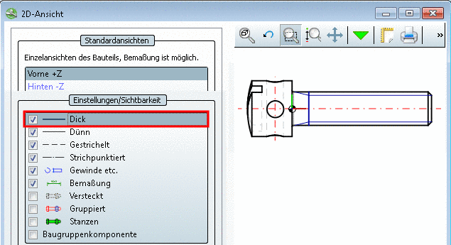
Thick Lines shall be created on the layer AM_0 in red.
Under Layer Configuration, in the block Thick Solid Lines the value in the key AcadLayerLineColor_00 is set on 1 (=red).[47]
;----- Layer Configuration -----
;Thick Solid Lines
AcadLayerName_00=AM_0
AcadLayerLineType_00=Continuous
AcadLayerLineColor_00=1
AcadLayerLineWeight_00=50
AcadLayerVisibility_00=1
-
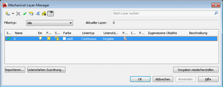
The layer AM_0 is not existing in AutoCAD.
The layer "AM_0" is created in AutoCAD with the defaults from the configuration file.
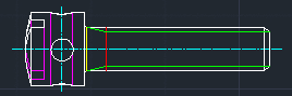
The thick lines are depicted in red color in AutoCAD.
-
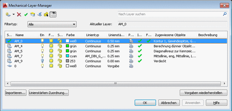
The layer AM_0 is available in AutoCAD and is set on white.
The inserted part is depicted with white "Thick line", because AutoCAD has priority.