Login
Our 3D CAD supplier models have been moved to 3Dfindit.com, the new visual search engine for 3D CAD, CAE & BIM models.
You can log in there with your existing account of this site.
The content remains free of charge.

Top Links
Categories


Search FAQs
Most Recent FAQs
-
0 comments, 0 likes, 3,443 views100% helpful.
-
0 comments, 0 likes, 4,645 views100% helpful.
-
0 comments, 0 likes, 10,445 views
Most Viewed FAQs
-
0 comments, 0 likes, 128,997 views0% helpful.
-
0 comments, 0 likes, 23,804 views
-
0 comments, 0 likes, 21,201 views18% helpful.
FAQs
-
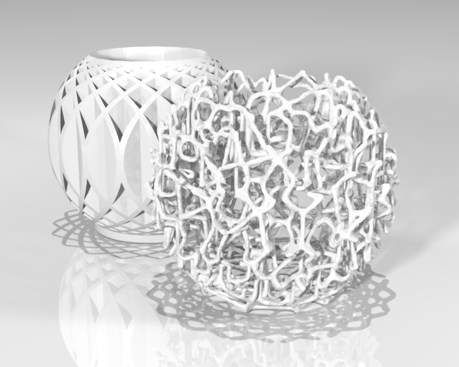
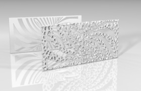
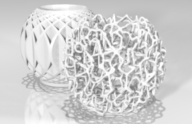
About this service - http://www.voronator.com/ Supported formats Currently supported formats for input are:...
About this service - http://www.voronator.com/
Supported formats
Currently supported formats for input are:
As output format we provide STL and PLY (both binary only).STL Stereolithography binary and ASCII PLY Stanford Polygon Library DAE Collada OBJ Wavefront Object OFF Object File Format The result is rubbish!
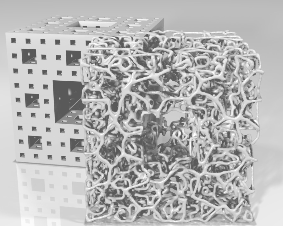
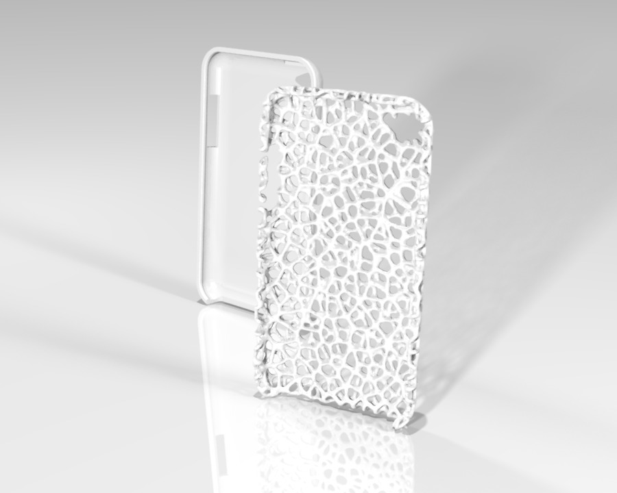
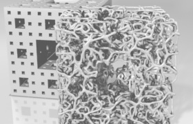
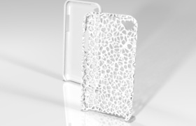
Yeah, that can happen. Not all models are suitable for our Voronoization process.
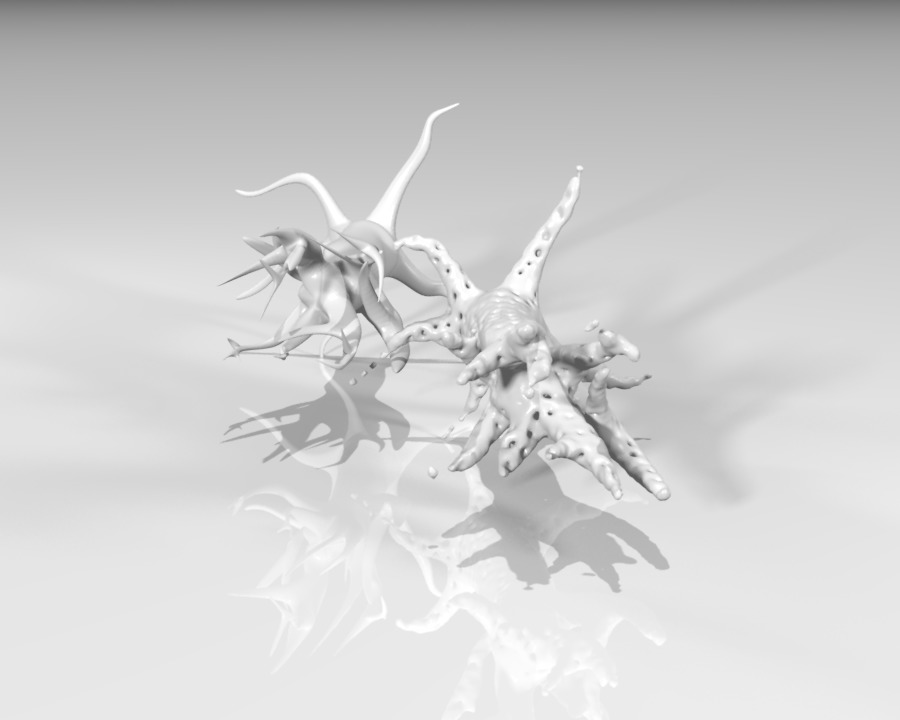
Take a look at the following models to get an idea what kind of models will not work.
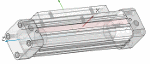
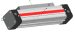
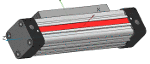
Models with thin solids or convoluted structures will not work with our Voronoization process.

 Permalink | 0 comments, 2 likes, 6,560 viewsWas this answer helpful?
 -
Upload your 3D CAD models for free on PARTcloud.net and show them to your friends and co-workers with the PARTcloud.net app - IT IS FREE ...
Upload your 3D CAD models for free on PARTcloud.net and show them to your friends and co-workers with the PARTcloud.net app - IT IS FREE and FOR YOU !
The App's Features:
- Sketch search for finding any part easily
- Mixed reality with your 3D part
- See your 3D part as anaglyph red/cyan model


 Permalink | 0 comments, 0 likes, 5,001 viewsWas this answer helpful?
 -
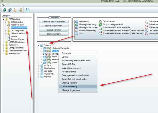
Remove catalog PARTadmin -> Index administration -> open folder Catalogs -> choose with right mousebutton catalogthat should be...
-
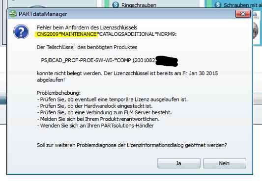
This message means that a licensefile is in use which date of maintenance expired. Solutions: 1. Usage of valid licensefile and make su...
This message means that a licensefile is in use which date of maintenance expired.
Solutions:
1. Usage of valid licensefile and make sure this is the only/ unique licensefile used (press F1-button in PARTsolutions
for documentation).if you do not have a valid licensefile:
2. Contact your local PARTsolutionsdealer to receive actual licensefile.
3. Contact your local PARTsolutionsdealer for renewal of maintenancecontract.
 Permalink | 0 comments, 0 likes, 13,394 viewsWas this answer helpful?
 -
catalogs >= 1.5 GB cannot be installed via PARTadmin - online (->PSOL 10.0 SP0) Please use PSOL >= 10.0 SP1 or download catalog...
-
Please add the domains *.partcommunity.com *.partserver.de to your list of trusted websites: eg. Internet Explor...
*.partcommunity.com
*.partserver.de
to your list of trusted websites:
eg.
Internet Explorer -> Tools -> Internet Options -> Security -> Trusted Sites
Alternatively you can also try to use a different browser.
Contact your local IT for help changing settings if necessary!
If the proposals do not work please contact the support of the partner portal directly, because sometimes Free mail addresses like abc@gmx.de are blocked by our partner portals.
X
Permalink | 1 comment, 0 likes, 9,570 viewsWas this answer helpful? -
Follow the steps listed below to integrate the chosen CAD model into your CAD system directly: Make sure that you are in the d...
Follow the steps listed below to integrate the chosen CAD model into your CAD system directly:
-
Make sure that you are in the dialog area 3D CAD CATALOGS and navigate to the required part.
-
In the dialog area Download CAD models under Edit CAD formats -> Add CAD formats, select the transfer mode directIntoCad by clicking into the option field. Then define the CAD system and confirm your entries by clicking on Save.
-> The view returns to the dialog area Generation options / Selected formats. Confirm your entries by clicking on Save.
-
Under Actions, click on Generate CAD model.
-> The information dialog Generating CAD models opens.
Note
All formats activated under Download CAD models(dialog area 3D CAD CATALOGS) -> Edit CAD formats -> Selected Formats are generated and listed here now.
As long as the generation is running, is shown.
-
As soon as the generation has completed, you can submit the CAD models to the CAD system in this window directly by clicking the link Direct integration.
If you close this window, further CAD models can be selected.
Furthermore all generated CAD models are listed under Download CAD models.
-> In the transfer mode Direct integration into CAD system the link text in the column Actions will be the following:
-
By clicking the link Info specific part information is displayed:
-
Click on the link Direct integration or the symbol
 , in order to load parts into the CAD system.
Note
The application component PART2cad is required at the workstation when using direct integration.
Install it during the first run. The necessary installer opens automatically.
The installer itself needs Java.
-> Once Java is installed the PART2cad installation will start. If Java is not installed, there will be no Java logo displayed. In this case click on the link Click here and install Java.
-> Warning messages may show up. Let the component PART2cad install.
During the first run the direct integration PART2cad will be downloaded.
Following runs will open the dialog Transferring model to CAD. No user interaction is necessary.
-
In the drop-down menu select the CAD version where the model is to be transferred. Confirm the selection with Choose.
-> A dialog box "Export ..." is opened to select the destination directory.
-
Select the preferred destination directory. Use ... to browse. Confirm your entries by clicking Ok.
-> The model is transferred to the CAD system.

Note
When the transfer to the CAD system is finished a message will be shown.Please note the following selection dialog for the version name of the CAD system.
-> The part has been imported in the CAD system.
If the CAD system is not started or the wrong version was chosen, an error message will be shown.
Permalink | 0 comments, 0 likes, 8,126 viewsWas this answer helpful? -
-
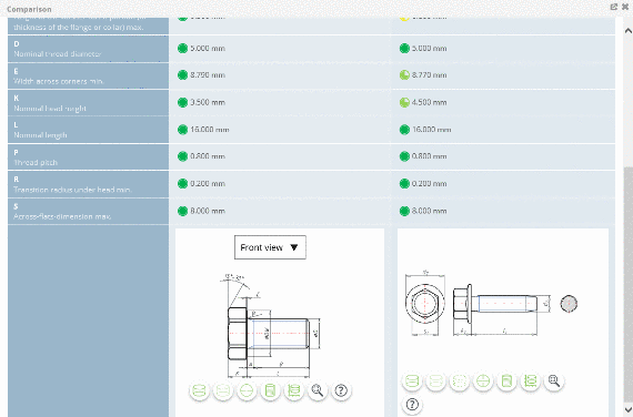
As soon as a CAD model has been selected, in the dialog area CAD model preview the Dimension diagram tabbed page show...
As soon as a CAD model has been selected, in the dialog area CAD model preview the
Dimension diagram tabbed page shows the 2D views.
Note
Always a default dimension view is displayed (created for a middle row) and this may differ from your selected part.
-
Under Actions click on Dimension diagram to get 2D views of the chosen part.
-
By clicking on a Preview you can select the desired dimensioning view.
-
In the toolbar, move the mouse pointer over the icons in order to receive information about the icons.
Permalink | 0 comments, 0 likes, 9,523 viewsWas this answer helpful? -
-
If you don't find the desired CAD model, you can let CADENAS know which your preferred catalog is. Therefore proceed as follows: ...
If you don't find the desired CAD model, you can let CADENAS know which your preferred catalog is. Therefore proceed as follows:
Permalink | 0 comments, 0 likes, 9,621 viewsWas this answer helpful? -
Follow the steps listed below to carry out the geometric similarity search: Make sure that you are in the dialog area 3D CAD ...
Follow the steps listed below to carry out the geometric similarity search:
-
Make sure that you are in the dialog area 3D CAD CATALOGS and search for the required part.
-
At directory level
 select product groups as long as a concrete assembly
  or concrete single part
  has been specified. Select the desired part by clicking into the option button before the desired row.
-
Click on Geometrical Search.

-> The similar parts found are listed in the dialog area Results.
Permalink | 0 comments, 0 likes, 9,007 viewsWas this answer helpful? -
-
Some parts contain value range fields. In order to completely specify the part, a selection must be made in the value range fields. ...
Some parts contain value range fields. In order to completely specify the part, a selection must be made in the value range fields.
The settings are made in the Variables section.
Follow the steps listed below to set the value ranges:
-
Make sure that you are in the dialog area 3D CAD CATALOGS and search for the required part.
-
At directory level
select product groups as long as a concrete assembly or concrete single part has been specified. Select the desired part by clicking into the option button before the desired row. -
Click on the part description in order to reach the variable view.

-> You will recognize the value range fields based on their yellow background color.
There are different types of value range fields:- List fields
Using the arrow open the value range field and select the desired value.

Then select the desired value.

- Input fields or selection via slider
Enter the desired value manually or set it using the slider in the given area.
Note
Inputs outside of the allowed value range are automatically corrected.
- Value range fields with images
Some catalogs support images for variant selection.
Click on the image in order to set another value.
-> A dialog opens for choosing the characteristic per image.
Select the desired variant by clicking on the image.
-> It is reloaded into the variable view.
If you do not want to take over the changes, click on x.
The part is now completely specified.
Permalink | 0 comments, 0 likes, 7,652 viewsWas this answer helpful? -
-
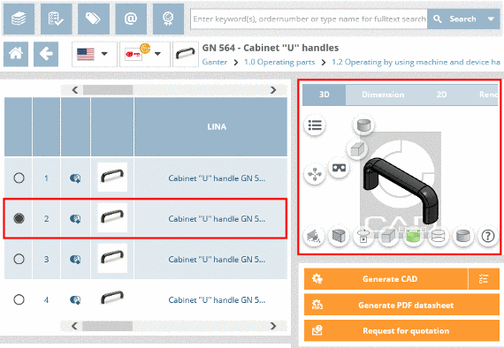
Follow the steps listed below to define the characteristic of the part: Make sure that you are in the dialog area 3D CAD ...
Follow the steps listed below to define the characteristic of the part:
-
Make sure that you are in the dialog area 3D CAD CATALOGS and search for the required part.
-
At directory level
select product groups as long as a concrete assembly or concrete single part has been specified and choose an assembly or a single part.
-
Define the characteristic of the part, by clicking into the option field of the desired row.
-> A default view of the selected model which may differ from the selected characteristic, is displayed under CAD model preview.
Note
If you want to view an exact replication of the characteristic, under Actions click on Generate preview.
-
Switch to the variable view by clicking on the part description.
-
The variable view shows all important data of a specific characteristic in a compact form.
Permalink | 0 comments, 0 likes, 9,463 viewsWas this answer helpful? -
-
Follow the steps listed below to generate a PDF datasheet: Make sure that you are in the dialog area 3D CAD CATALOGS and select t...
Follow the steps listed below to generate a PDF datasheet:
- Make sure that you are in the dialog area 3D CAD CATALOGS and select the desired catalog.
- At directory level
 select product groups as long as a concrete assembly
 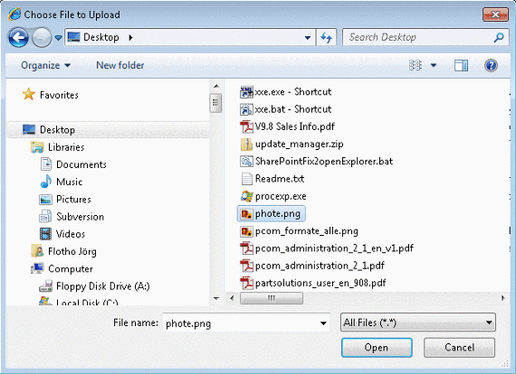 or concrete single part
  has been specified.
-> As soon as a concrete row has been determined, a 3D view and dimensional drawings are loaded under CAD model preview.
- Under Actions, click on Generate PDF datasheet.
- The information dialog Generation CAD models opens.
Note
If the CAD model shall be generated in several formats under Format selection there is the possibility to choose the format PDF Datasheet additionally. By holding down the CTRL key, you can make multiple selections.

- Under Actions, click on Generate CAD model.
- The information dialog Generating CAD models opens.
-> The generation was started.
The following symbols show the generation status: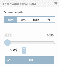 Active generation
 Generation erroneous
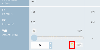 Generation successfull. Part ready for download.
Note
The pregenerated 3D PDF corresponds to a sample part (created for a mid-row with standard setting) and may differ from your selected part.
Permalink | 0 comments, 0 likes, 9,138 viewsWas this answer helpful? -
Follow the steps listed below to send a request for quotation: Make sure that you are in the dialog are 3D CAD CATALOGS and sele...
Follow the steps listed below to send a request for quotation:
- Make sure that you are in the dialog are 3D CAD CATALOGS and select the desired catalog.
- At directory level select product groups as long as a concrete assembly or concrete single part
 has been specified.
-> As soon as a concrete row has been determined, a 3D view and dimensional drawings are loaded under CAD model preview. - Under Actions click on Request for quotation.

-> The dialog for inputting your quotation request opens.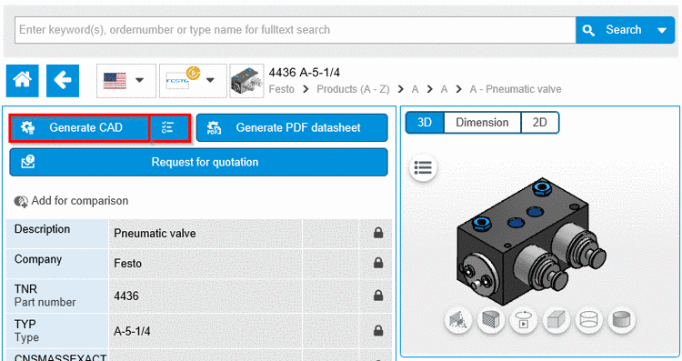
Fill in the input fields completely and click on Send request, to send the request. 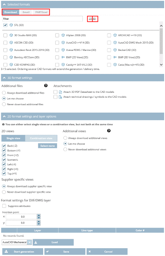
Note
In order to get a preview of your enquiry click on Preview request.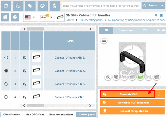
-> A dialog box with a preview of the request opens.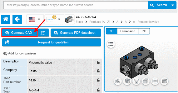
- As soon as the e-mail was sent, you will receive the confirmation Email has been sent successfully.

Permalink | 0 comments, 0 likes, 8,176 viewsWas this answer helpful? -
Under 3D CAD CATALOGS you have the possibility to chooses CAD formats and to define the handing over mode into the CAD system. 1. ...Under 3D CAD CATALOGS you have the possibility to chooses CAD formats and to define the handing over mode into the CAD system.
1. Make sure that you are in the dialog area 3D CAD CATALOGS.2. On the right side under Actions, click on Edit CAD formats

-> The following dialog are shows up:
- Generation options (Level of Detail)
- Selected Formats (Add CAD formats)
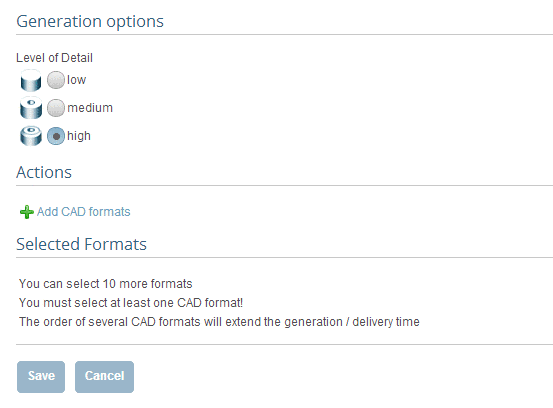 3. Click on Add CAD formats.
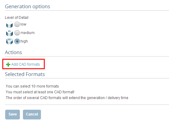 -> The settings area for Generation type and Format selection opens.
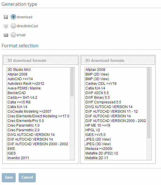 4. First determine the desired generation type. Click into the desired option field.
-> In the dialog area Format selection select a format or several formats.5. Click on Save.
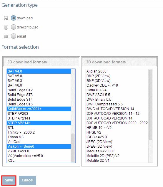
-> The view changes back to the dialog area Generation options / Selected formats.
In the dialog area Selected Formats you can see your current selection.
In addition to that under Actions you can define the Level of Detail.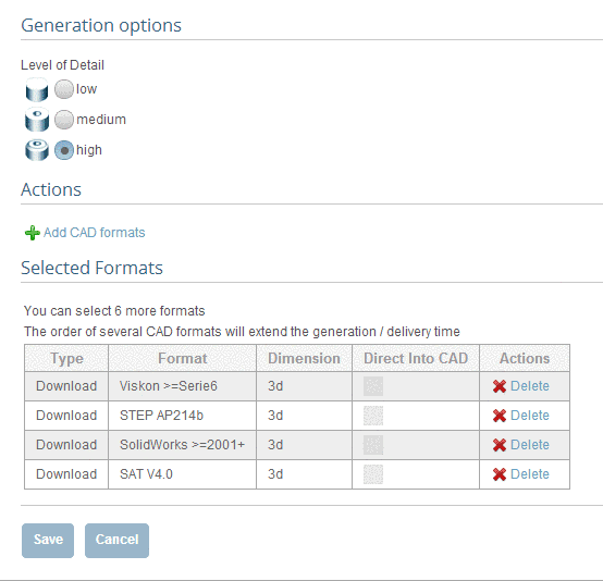 6. Confirm your entries with Save.
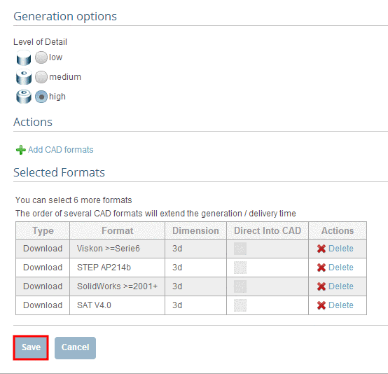 Permalink | 0 comments, 0 likes, 9,149 viewsWas this answer helpful?
 -
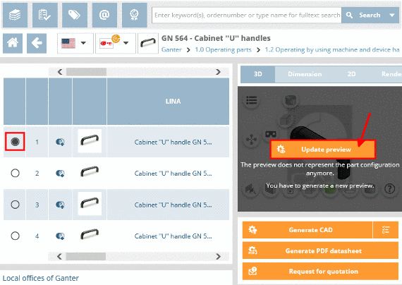
As soon as a part has been specified, the 3D preview shows up in the CAD model preview area CAD model preview. NoteA pregenerated d...
As soon as a part has been specified, the 3D preview shows up in the CAD model preview area CAD model preview.
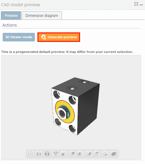
Note
A pregenerated default preview is shown, which may differ from your current selection. If you want to see the fitting 3D view, that matches your characteristics, click on Generate preview in the Actions dialog ara.
The following explains the individual buttons of the 3D view:
Permalink | 0 comments, 0 likes, 2,288 viewsWas this answer helpful? -
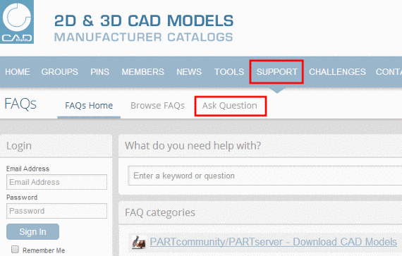
If you have forgotten the e-mail address which you have chosen during the registration please contact the support team via Ask Quest...
If you have forgotten the e-mail address which you have chosen during the registration please contact the support team via Ask Question in the FAQ area.
Permalink | 1 comment, 0 likes, 1,501 viewsWas this answer helpful? -
Log in with your access data and click on the button My Profile. On the right side, under Profile Options, cli...
-
Log in with your access data and click on the button My Profile.
-
On the right side, under Profile Options, click on Edit My Profile.
Permalink | 0 comments, 0 likes, 8,430 viewsWas this answer helpful? -
-
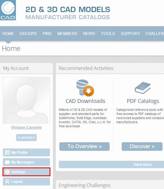
1. Log in with your access data and click on the button Settings. 2. Click inside the field Email Address and enter your new e-m...
1. Log in with your access data and click on the button Settings.
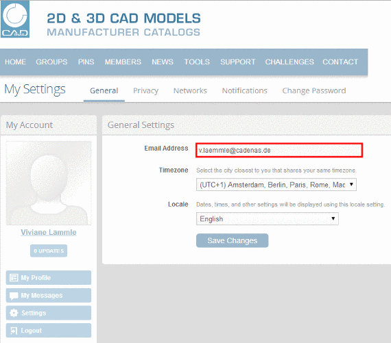
2. Click inside the field Email Address and enter your new e-mail address.
3. Confirm the data by clicking the button Save Changes.
-> The confirmation Settings were successfully saved is displayed.
Permalink | 2 comments, 0 likes, 8,390 viewsWas this answer helpful? -
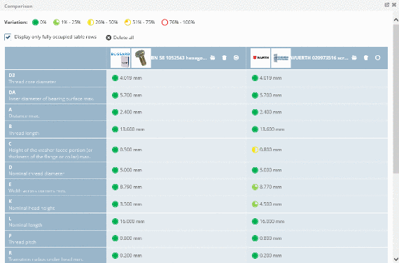
Overview to the quality characteristics Gold Quality Seal Available in many languages Levels of detail included (LOD...