powered by CADENAS

Manual

Manual

3.1.20.6.2.3. Context menu commands in docking window "2D derivation"

Context menu: Single part - 2D derivation

Context menu: Single part - 2D derivation

  • Zoom all:

    With the Zoom all button you bring the display of the part onto a balanced measurement. The part is large enough, but still does not protrude over the 3D view window during rotation. If the option Explicit zoom has been set (see Section 3.3.8.4.1, “ Handling ”) the display within the window is maximally enlarged.

  • Undo zoom

  • Zoom on window | Zoom in/out | Pan

    [Note] Note

    The basic assignment of mouse keys happens under PARTdataManager - > Extras -> Settings... -> 3D settings -> Mouse and keyboard. Details on this can be found under Section 3.3.8.4.2, “ Mouse and keyboard assignment”.

    Via context menu command, you can change the assignment of left mouse key.

    • Zoom on window: Enlarge by drawing a rectangle.

  • Choose insertion point

  • Show coordinate system

  • Print

  • Dimensioning mode

3.1.20.6.2.3.1.  Choose insertion point

Turn on the option by clicking on the menu item.

As soon as you move your cursor over a possible insertion point, a catch shows up. Confirm the selection by clicking once.

--> The insertion point is displayed with a green arrow.

Turn off the option by selecting another menu item.

Information about Insertion point can also be found under Chapter 7, PARTdesigner parametric tool in eCATALOGsolutions Manual and Chapter 9, Configurator (Assemblies in PARTdataManager) in eCATALOGsolutions Manual.

[Note] Note

With enabled dimensioining mode the command is inactive.

3.1.20.6.2.3.2.  Show coordinate system

Show coordinate system shows a measuring scale horizontally and vertically.

3.1.20.6.2.3.3.  Print

You have the opportunity to print the 3D view of the part/assembly.

When clicking on the command the respective settings dialog box of your operation system opens.

3.1.20.6.2.3.4.  Dimensioning mode

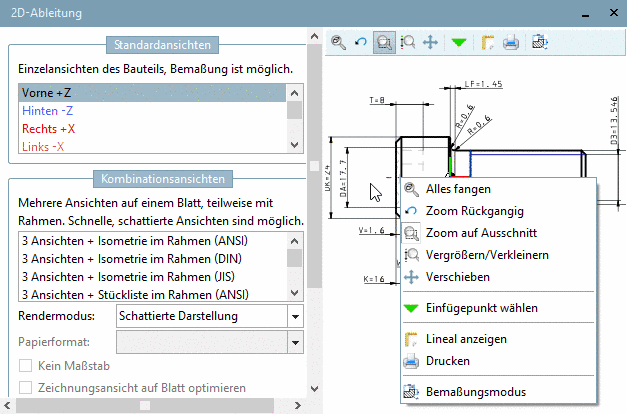
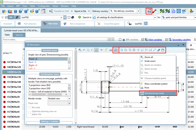
The dimensioning mode can be reached in different ways:

  • Via PARTdataManager -> button 2D derivation -> docking window 2D derivation -> context menu command Dimensioning mode or alternatively icon Dimensioning mode .

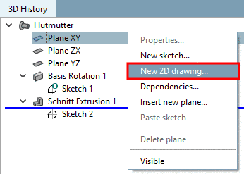
  • Via PARTdesigner -> docking window 3D History -> context menu Plane -> New 2D drawing...

    Call New 2D drawing...

    Call New 2D drawing...

    -> A view with Sketch history and Sketcher is opened.

    Dimensioning mode in Sketcher

    Dimensioning mode in Sketcher

  • Via PARTdesigner -> File menu -> New drawing

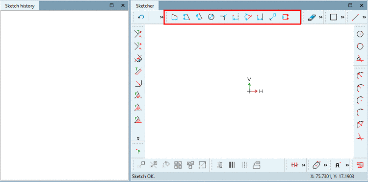
In the following the single functions of Dimensioning mode are explained.

Horizontal dimensioning at 2 points:

  1. Press the button.

  2. Click on the first point. Take care to notice that a dot is only then attached when the snap is shown.

  3. Click on the second point.

  4. Click on the place where the dimensioning should be placed.

  5. Change parameter dialog box: Set the Measure text (the expression {AUTOMATIC%0} stands for the measured value), the Offset (spacing between dimensioning text and measured line) the Height (font size of the dimensioning text) and the Arrow size.

Height: 3.5; Offset: 5.58...; Arrow size: 3.5

Height: 3.5; Offset: 5.58...; Arrow size: 3.5

Change parameter

Change parameter

Vertical dimensioning at 2 points:

See Horizontal dimensioning at 2 points

Parallel dimensioning at 2 points:

See Horizontal dimensioning at 2 points

Diameter with angle and distance:

  1. Press the button.

  2. Click on the circle to be dimensioned. --> The dimensional line shows up.

  3. Position your dimensions.

Version 1: Fix the Angle of the line with a simple mouse click. Then pull the entire dimensioning onto the desired Position and deposit it with a mouse click.

Version 2: Fix the angle and position of the dimensioning with a double mouse click in one step.

[Note] Note

You can change the angle (concerning the x-axis) of the dimensioning in the Change parameter window.

Variant 1

Variant 1

Variant 2

Variant 2

Change parameter

Change parameter

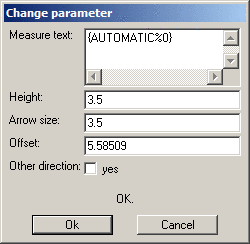
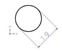
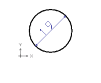
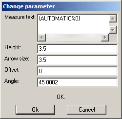
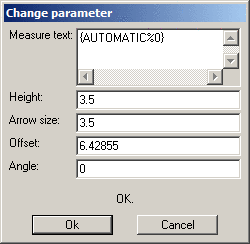
Radial dimensioning with angle and distance:

  1. Press the button.

  2. Click on the to be dimensioned circle, respectively the arc of a circle. --> The dimensioning line shows up.

  3. Position your dimensioning.

The angle (concerning the x-axis) of the dimensioning can also be adjusted in the Change parameter window.

0° lays on the bisecting line of the segment of the circle.

Half value offset dimension from line:

  1. Press the button.

  2. Click on the reference line (axis of reflection).

  3. Click on the point, whose distance to the reference line should be dimensioned.

  4. Position the dimensioning.

    --> The Change parameter window is opened.

  5. Apply the dimensioning to the entry fields if needed.

[Note] Note

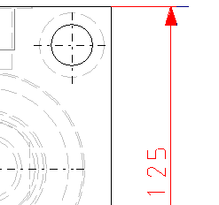
Rotationally symmetrical points are dimensioned from point to line with help of the half value function. Though the depicted dimension line only describes half of the dimensional length (therefore "Half value"), the dimensional value, however the whole dimensional length!

Angle dimensioning at 2 lines:

  1. Press the button.

  2. Click on the first line (pay attention to clockwise direction!).

  3. Click on the second line.

  4. Position the dimensioning. --> The Change parameter window opens.

  5. Apply the dimensioning to the entry fields if needed.

Distance dimensioning from point to line:

  1. Press the button.

  2. Click on the reference line.

  3. Click on the point whose distance to the reference line should be dimensioned.

  4. Position the dimensioning --> The Change parameter window opens.

  5. Apply the dimensioning to the entry fields if needed.

Delete dimensioning:

Please mark the desired dimensioning.

Dimensioning mode finishing

Adopts the entered dimensioning and leaves the dimensioning mode.

Saving dimensioning

A dimensioning can be saved as a 2D sketch (File template *.2db).

When you select a dimensioning it will show up in red and the context menu can be retrieved.

  • Change parameter...

    Re-open the Change parameter window.

  • Delete a step

  • Delete a step including attached steps