Manual
Login
Our 3D CAD supplier models have been moved to 3Dfindit.com, the new visual search engine for 3D CAD, CAE & BIM models.
You can log in there with your existing account of this site.
The content remains free of charge.

Top Links
Manual
 |
When clicking on
the icon Import drawing  , you can import an image of a part, then extract it
properly with the help of various methods and finally insert the drawing
into the sketches-cube in order to execute a Sketch search (2D).
, you can import an image of a part, then extract it
properly with the help of various methods and finally insert the drawing
into the sketches-cube in order to execute a Sketch search (2D).
In the following the procedure is shown by means of an example:
-
-> The same-named dialog box opens.
-
Click on the icon Import drawing
and insert the desired image via Explorer.
(Possible image formats are image formats are jpg, gif and png.) Just as well
you can insert the image directly with Ctrl+V-> The dialog box Extraction of the part is opened with imported image.
-
Determine the method of extraction by clicking on the respective tab and extract the part.
-

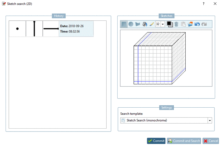
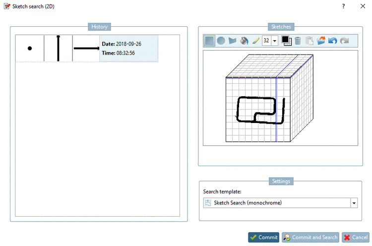
If desired, you can modify the sketch now. Compare Section 3.1.6.4.6.6, “ Drawing Tools”.
Close the dialog box Sketch search (2D) by clicking on or .
In the following the methods of extraction namely Default, Segmentation and Cut are described in detail.
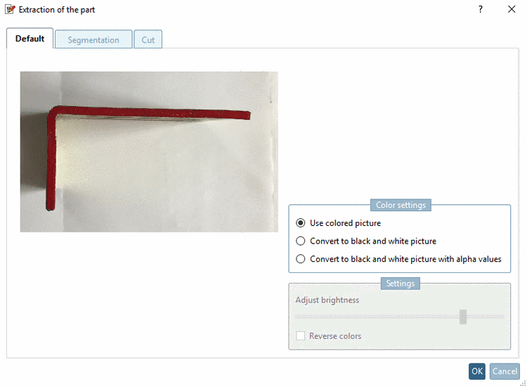
The Default method offers the following options:
Use colored picture: The picture should show the contour without any shades, then it can directly be used.
-
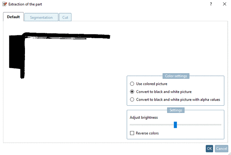
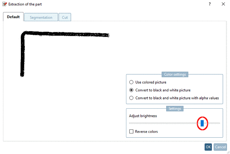
Convert to black and white picture: Adjust brightness as long as the desired contour becomes visible.
Convert to black and white picture with alpha values: This option works for pictures containing transparency. All transparent pixels are set to white, all non-transparent to black.
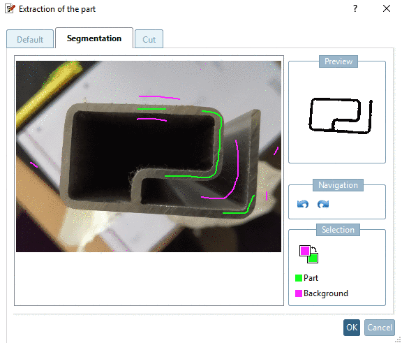
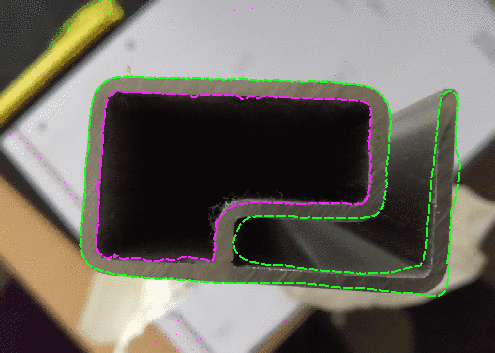
Using the Segmentation tool, a segment of the part or background can be marked as often as desired, until the result is satisfying.
Generally applies that high-contrast images with little interfering contours need less markings for the extraction of the drawing. In practice it's difficult to make perfect pictures. But the tool is designed to remove interfering contours easily.
![[Note]](/community/externals/manuals/%24%7Bb2b:MANUALPATH/images/note.png)
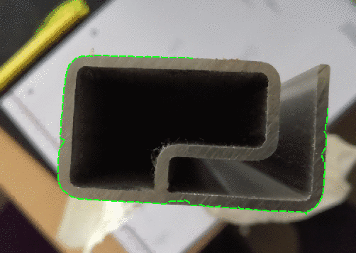
The most important contours are displayed in the preview with only little markings.

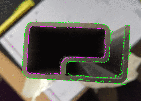
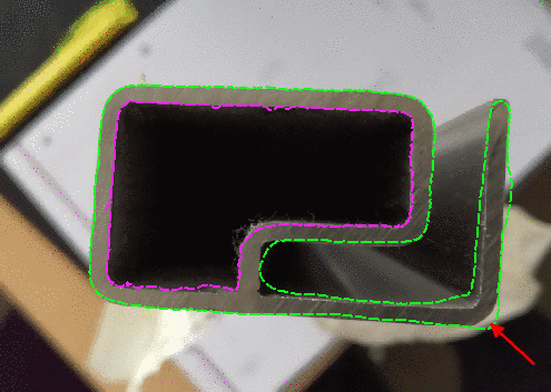
Especially the low-contrast intermediate area is not correctly displayed yet. Mark the intermediate area with purple.

-> Thereby also areas of the part itself are removed (here in this example).
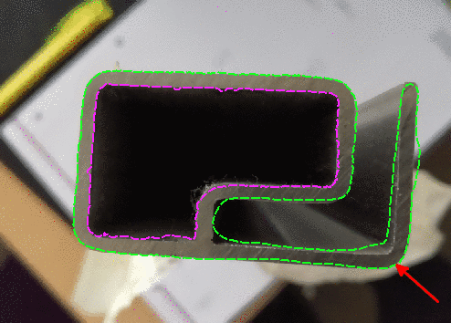
Add the missing part areas by using green.

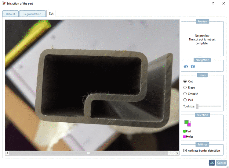
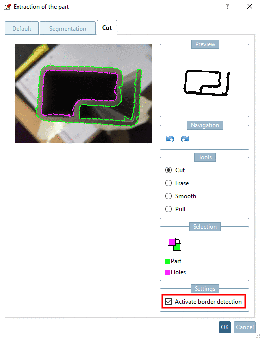
Mark the outer (green = part) and inner contour (purple = holes) of the part, either as freehand line or with the option Activate border detection (mostly better).
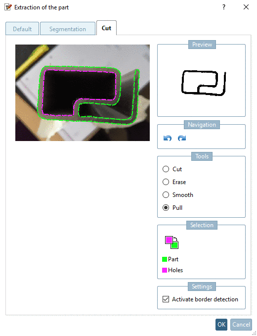
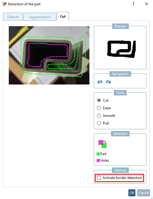
For this you can use the tools Cut, Erase, Smooth and Pull:
-
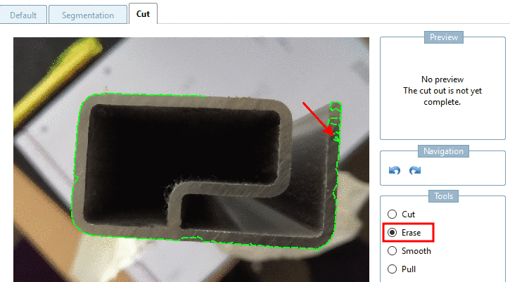
Erase: Erase only works at the end of a line (not between).
Click on the end of the desired line and erase along the line with pressed mouse key.
-
Line Points are moved to the expected average value between previous and subsequent point.
-
Pull line points closer to the mouse pointer. When clicking outside of the contour, you will pull it outward, when clicking inside then inward. Each click brings the line closer to the mouse pointer.

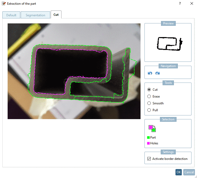
Activate border detection: If the option is deactivated, please try to follow the contours as exactly as possible. The result will be taken as it is.
Normally a good result is easier achieved with activated option.
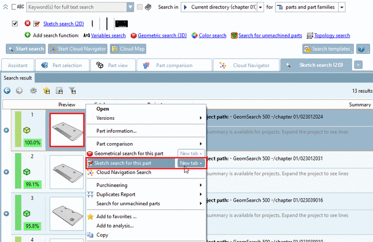
You can automatically create the sketch views from any part of the index tree or a result list, afterwards modify in the sketcher and then use for a sketch search.
-
Start: Click on the Sketch search for this part context menu command.
You can find the command in the context menu of projects (in the index tree or result lists).
-
3 sketch views are automatically generated and displayed in the Import drawing dialog box.
If the Convert to black-and-white image option is activated, you can optionally use the Reverse colors and Adjust lightness function before the import.
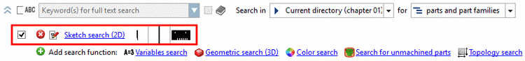
With the drawings are overtaken and displayed in the list of search methods.
-
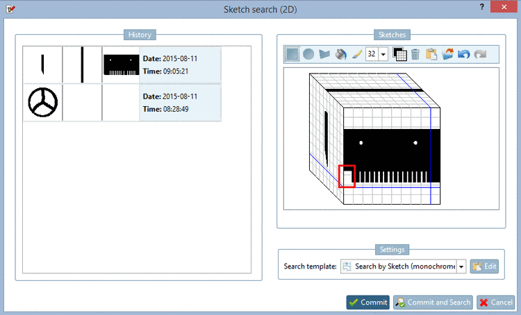
When clicking on the link Sketch search (2D) the dialog box to edit the sketches opens. Now you can use the sketches in the current state or optionally modify them first and then use them for the "Sketch search (2D)".
You can find details on the sketcher under Section 3.1.6.4.6.6, “ Drawing Tools”.

Create sketches manually in the sketcher. See Section 3.1.6.4.6.6, “ Drawing Tools”.
