Manual
Login
Our 3D CAD supplier models have been moved to 3Dfindit.com, the new visual search engine for 3D CAD, CAE & BIM models.
You can log in there with your existing account of this site.
The content remains free of charge.

Top Links
Manual
 |
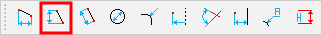
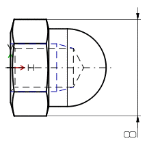
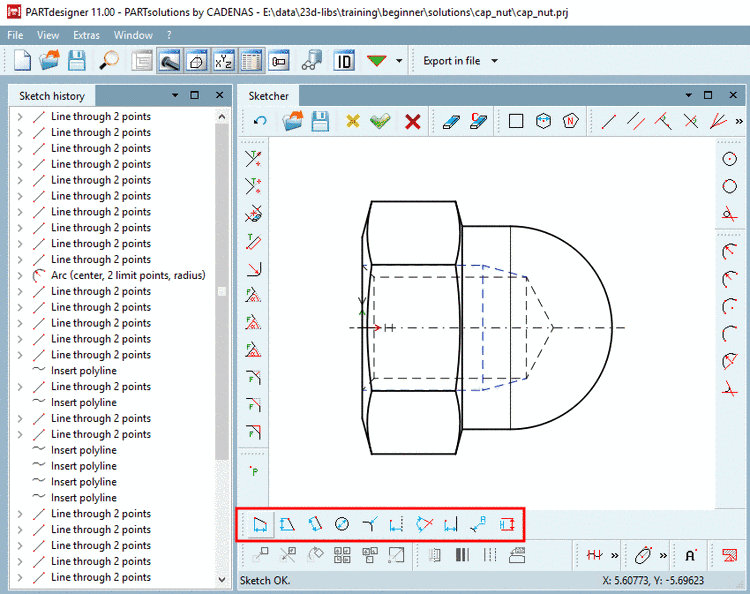
With the help of respective buttons the *.3db object can be dimensioned in the Sketcher.
-
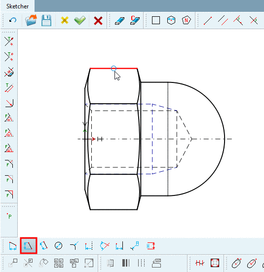
For example, if you want to enter a vertical dimensioning (here key size), then in the Dimensioning toolbar, click on the button Vertical dimensioning at 2 points.
-
Move the mouse pointer to the first line until the snap appears and click to set.
-
Draw the dimension line at the desired position and fix it by mouse click.
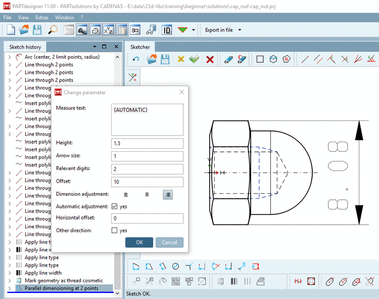
-> The dimension lines and the dialog box Change parameter become visible.
-
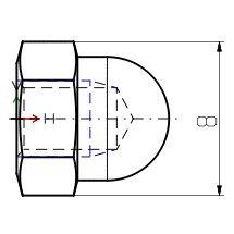
Determine the single parameters:
-
By default, "{AUTOMATIC}" is displayed in curly braces.
"AUTOMATIC" takes the current value from the geometry.
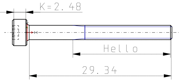
Define a static or dynamic or mixed static-dynamic Dimension text.
Hello
Dimension text: static-dynamic
K={K}Only enter the desired variable. The respective value is dynamically generated.
{L} Relevant digits: Specification of the displayed Decimal digits of Dimension text.
-
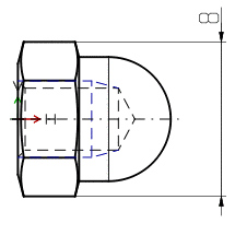
Horizontal offset: The value determines the horizontal text shift from center.
Other direction: The dimensioning line is positioned on the other side of the element.
![[Note]](/community/externals/manuals/%24%7Bb2b:MANUALPATH/images/note.png)
Note To satisfy high design demands, you can create external preview pictures and provide it as *.pra file for example. On this see Section 5.12.2, “External creation and import/conversion of Dimensioning views ”.
-
-
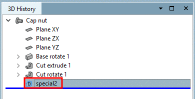
Click on the Accept changes
 button.
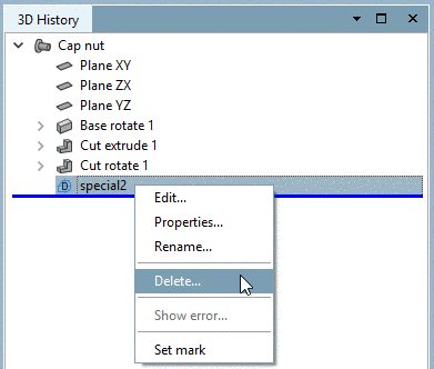
-> The newly created view will be displayed in the 3D History area.
With the context menu command Delete... you can delete additionally created dimensioning views.
-
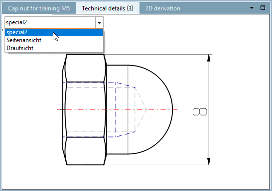
Open the part in PARTdataManager.
-> The self-created dimensioning view is now available under Technical details.