Manual
Login
Our 3D CAD supplier models have been moved to 3Dfindit.com, the new visual search engine for 3D CAD, CAE & BIM models.
You can log in there with your existing account of this site.
The content remains free of charge.

Top Links
Manual
 |
In rotated patterns the borings are circularly arranged around a central point.
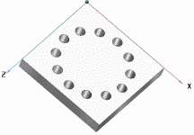
The following example shows the design process of a rotated pattern step by step in detail.
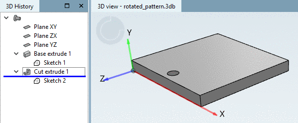
Initial situation: The origin boring is already created by Cut extrude (Sketch 2). It shall be copied in circular form so that 12 borings are created in total.
-
Open the sketch containing the origin boring and set the pattern origin on the boring via button Pattern origin..
-
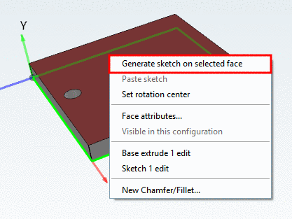
Via Generate sketch on selected face, create a new sketch for the pattern.
-
In this sketch, set the starting point for the pattern design exactly at the same place, where the pattern origin is in the other sketch.
-
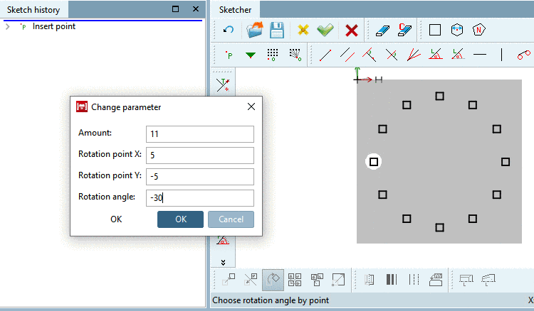
With pressed Ctrl key, click on the button Rotate selection
 .
.
Follow the notes in status line:
-
Adjust the values in input fields for Amount, Rotation point and Rotation angle and confirm with .
-
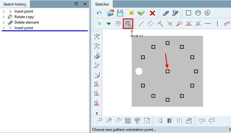
Delete the base point via Delete element
 , because it would be created twice otherwise. The
base point is in another sketch.
, because it would be created twice otherwise. The
base point is in another sketch. -
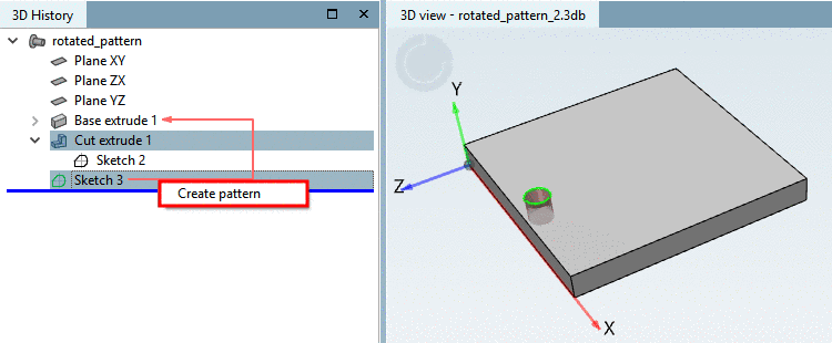
In 3D History, mark the design steps Cut extrude and the sketch, which contains the pattern (here in example Sketch 3) and in the context menu, click Create pattern.
-> The borings are copied according to the pattern.
-
Align borings to reference point

![[Note]](/community/externals/manuals/%24%7Bb2b:MANUALPATH/images/note.png)