Manual
Login
Our 3D CAD supplier models have been moved to 3Dfindit.com, the new visual search engine for 3D CAD, CAE & BIM models.
You can log in there with your existing account of this site.
The content remains free of charge.

Top Links
Manual
 |
For the process of modelling in eCATALOGsolutions there are 2 methods available in order to manipulate the orientation of axes and the orientation of the part within space:
-
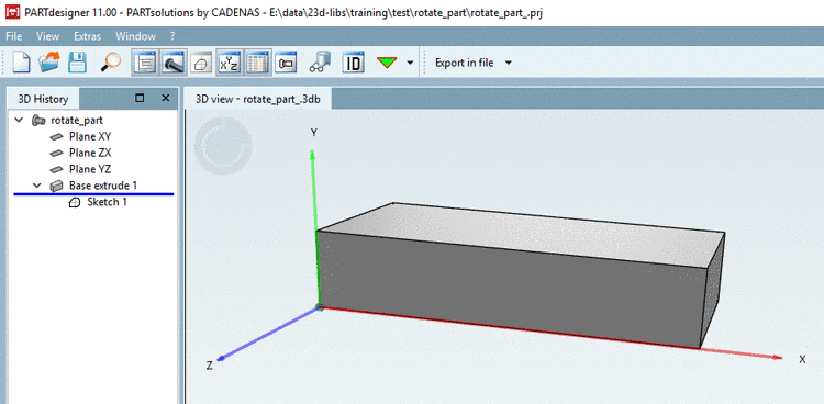
Initial situation: Part modelled in eCATALOGsolutions, with "incorrect" Y axis showing upwards.
Request: The part shall retain its lying position within space, but the coordinate system shall get a new orientation with Z axis showing upwards.
-
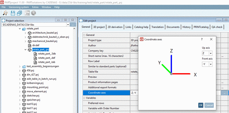
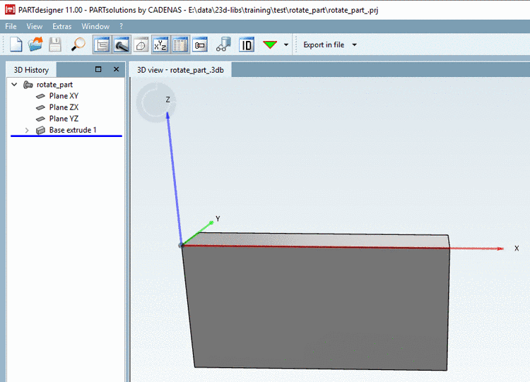
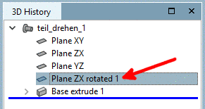
The coordinate system gets a new orientation in PARTproject via function Coordinate axes, so that the Z axis shows upwards and the Y axis backwards.
-
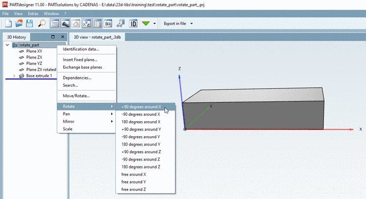
In PARTdesigner, via Rotate, the part can be brought into its original position within space.
In the 3D History, on part level, you can find the context menu command Rotate. After using +90 degrees around X the part is displayed in its original position again. Compare Fig. „Initial situation“.
![[Note]](/community/externals/manuals/%24%7Bb2b:MANUALPATH/images/note.png)
Note Rotate in PARTdesigner only works for fully modelled parts, not for Q&S parts.
The orientation of Q&S parts can be manipulated in the project file. There you can find a string starting with
REF1@MATRIX. Generalized: Calculate rotation matrix and multiply both matrices. For the calculation, there are help pages in the web:http://danceswithcode.net/engineeringnotes/rotations_in_3d/demo3D/rotations_in_3d_tool.htmlorhttps://matrix.reshish.com/de/multiplication.php.Changes don't become visible in PARTdesigner, but only in PARTdataManager.