Manual
Login
Our 3D CAD supplier models have been moved to 3Dfindit.com, the new visual search engine for 3D CAD, CAE & BIM models.
You can log in there with your existing account of this site.
The content remains free of charge.

Top Links
Manual
 |
In the following the characteristics / modeling rules will be described for each target system:
-
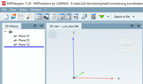
The parts must be located with the Z-axis to the top and with the Y-axis to the back (left in the isometric view)
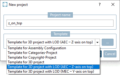
When creating the project select the template "Template for 3D project with LOD (AEC – Z-axis on top)".
The parts require the Placement Classification (see Section 5.13.8, “ Classify standard parts for placement dialog ”)
The parts should be equipped with a changeable Level of Detail (also see below)
-
If possible it should be worked with regular bodies / simple shapes.
-
Avoid interpenetrating solids.
-
Symbol representation and layout definition
The CNS classification provides specific classes for symbol representation and layout:
Both layout and symbol representation describe abstractions of the physical 3D model. They differ both in regard to the level of abstraction and in regard to the focus conceptually. When layouts focus on the geometrical 2D representation of the physical model, symbol representations focus on the logical functionality of the model. Both concepts are not interchangeable.
Layout: According to ISO 5455:1979 layouts have the characteristic of a scale in particular, meaning the scaling factor between 2D representation and 3D model. This particularly means that for layouts sizes such as height and width can be defined, which are directly related to the 3D model.
Symbol representation: The symbol representation as logical description of a part's functionally is a deeper abstraction of the physical model, where all properties like height, width and depth, if referring to the 3D model, are being omitted. Only the circuit symbol is represented.
We can clarify the difference with the help of two transformers: The one feeds a power line, the other serves to charge the mobile phone. The layout display is very different, if the scaling factor is unchanged, which mirrors the different physical dimensions of the two transformers. In both cases the symbol representation could be the same. In the CNS classification, layouts are described by the class CNSCAX|GFX|LAYOUT and (logical) symbol representations by the class CNSCAX|GFX|SYMREP.
An example can be found under Section 5.13.11.2, “Symbol or Layout Representation in BIM Field”.
![[Note]](/community/externals/manuals/%24%7Bb2b:MANUALPATH/images/note.png)

Parts must be classified with CADENAS Revit classification (family template, placement information and other attributes) and „OmniClass 2006“ (on this see separate point Classification below).
It is not allowed to use features / radius smaller than 1.4 mm in modeling.
Use extrusion features and avoid rotation features - if possible.
-
Cut-rotations (e.g. chamfers) should also consider the 1.4mm tolerance
All kind of conductors, pipes, channels, etc. have to be modeled as “filled body” absolutely.
-
A Revit connection point (Revit Family Template Mapping) must be specified (please also see separate point Classification below).
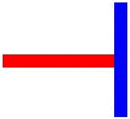
For the placement in Revit, the axes of the connection point will be used for positioning /orientation. Take care that axes orientation of the point is according to the axes in Revit (Z axis corresponds to orientation).
-
Revit connection points always have to be in the geometric center of gravity of a planar surface. Please also regard the orientation (Z axis) absolutely.
In order to be able to use definitions of light sources (*.ies files), parts have to be classified accordingly. See Section 3.5.3.1, “Revit: Load IES files in RFA (lighting fixtures)”.
-
In PARTS4CAD, classifications can be displayed on their own tab, which could be interesting especially when using a BIM CAD like Revit.
Details on the configuration can be found under Section 1.7.4.9.15, “Key "Tabs" - Adjust sequence and visibility of tabs (Part selection)” in PARTsolutions / PARTcommunity4Enterprise - Administration Manual.


-
The parts must be classified with IFC.
(See separate point Classification below.)
Use extrusion features – Avoid rotation features - if possible.
-
Absolutely avoid cut of edges (single edges should not touch each other):
-
It is not allowed to subtract volumes more than 1 time (cut features should not touch each other).
All parts should be tested with the “IfcCheckingTool”, see Further tests below.


