Manual
Login
Our 3D CAD supplier models have been moved to 3Dfindit.com, the new visual search engine for 3D CAD, CAE & BIM models.
You can log in there with your existing account of this site.
The content remains free of charge.

Top Links
Manual
 |
Symbol or layout representations can be found in different fields, among others in the BIM field. (Also see Section 5.13.10, “Classify Electrical Parts”.)
Both layout and symbol representation describe abstractions of the physical 3D model. They differ both in regard to the level of abstraction and in regard to the focus conceptually. When layouts focus on the geometrical 2D representation of the physical model, symbol representations focus on the logical functionality of the model. Both concepts are not interchangeable.
Layout: According to ISO 5455:1979 layouts have the characteristic of a scale in particular, meaning the scaling factor between 2D representation and 3D model. This particularly means that for layouts sizes such as height and width can be defined, which are directly related to the 3D model.
Symbol representation: The symbol representation as logical description of a part's functionally is a deeper abstraction of the physical model, where all properties like height, width and depth, if referring to the 3D model, are being omitted. Only the circuit symbol is represented.
We can clarify the difference with the help of two transformers: The one feeds a power line, the other serves to charge the mobile phone. The layout display is very different, if the scaling factor is unchanged, which mirrors the different physical dimensions of the two transformers. In both cases the symbol representation could be the same. In the CNS classification, layouts are described by the class CNSCAX|GFX|LAYOUT and (logical) symbol representations by the class CNSCAX|GFX|SYMREP.
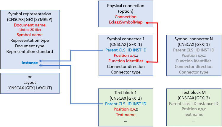
In the following example no physical connection is needed; furthermore no text blocks are used. Only the classes CNSCAX|GFX|1 (Symbol connector) and CNSCAX|GFX|SYMREP (Symbol representation) are used.
In the following a manual procedure is described, which can be automated as well:
-
Select the project to which you want to assign a certain symbol as additional export format. (In this example "c2fvvi412020.prj")
-
In PARTproject -> Edit project -> tabbed page General -> menu item General -> Additional export formats, click on the search button .
Under File path, enter the path to the desired DXF/DWG file. (Here "../../symbols/111102.dwg")
Under ID, enter the unique identifier, as it can be found in the source file (e.g. PDT). (Here "111102".)
-
-> The DXF/DWG file is now inserted under Additional export formats.
-
Open the Classification (CNS) by clicking on the search button .
-
Set the classes CNSCAX|GFX|SYMREP (Symbol representation) and CNSCAX|GFX|1 (Symbol connector) and for each, enter the instance number.
Close the dialog and click on .
-
Open Attributes (CNS) by clicking on the search button .
-
In the attribute CNS_DOC_CNSURI, enter the ID of the additional file with following syntax.
ADDFILE://ID
Again use exactly respective ID from the source file (e.g. PDT). (Here "111102".)
Under CNS_DOC_NAME, enter the file name of the DXF/DWG file.
-
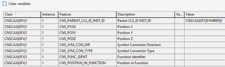
Create the connection between Symbol connector (CNSCAX|GFX|1) and Symbol representation (CNSCAX|GFX|SYMREP), namely by the value of the attribute Parent CLS_ID INST_ID. The last value of the string is the respective instance of CNSCAX|GFX|SYMREP.
Class "CNSCAX|GFX|1" with attribute "Parent CLS_ID INST_ID" and value "CNSCAX|GFX|SYMREP||<Instance>"
Fill out the required attributes of CNSCAX|GFX|1 and CNSCAX|GFX|SYMREP (if needed).
-
If all entries are made, the part can be exported to the CAD.