Manual
Login
Our 3D CAD supplier models have been moved to 3Dfindit.com, the new visual search engine for 3D CAD, CAE & BIM models.
You can log in there with your existing account of this site.
The content remains free of charge.

Top Links
Manual
 |
- 7.9.3.10.1.5.1. All blends, whose edges meet, have to be made as one blend
- 7.9.3.10.1.5.2. Blends in pattern
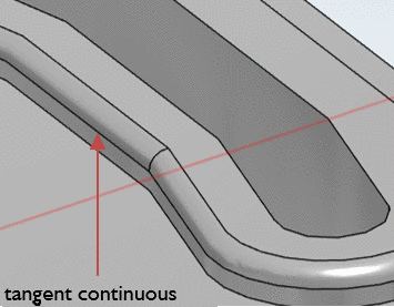
- 7.9.3.10.1.5.3. Tangent continuous
- 7.9.3.10.1.5.4. Preview presentation for Chamfer/Fillet
- 7.9.3.10.1.5.5. Face selection
- 7.9.3.10.1.5.6. Combination of Sweep and Blend
- 7.9.3.10.1.5.7. Depiction of Chamfer/Fillet in different CAD systems
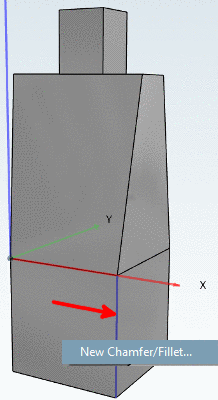
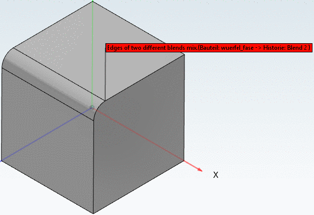
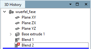
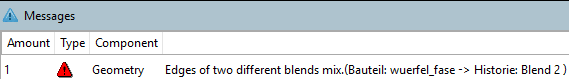
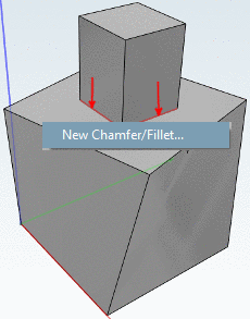
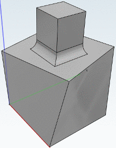
All blends, whose edges meet, have to be made as one blend. So the command New Chamfer/Fillet... can only be used initially. For further Blends the command Insert edge(s) to 'Blend xy' ... has to be used, otherwise an error message is displayed - even if the Blends have the same sizes (see following figures).
It is recommended to do all blends, whose edges meet, in one step. Otherwise, the performance of the Blend Feature can be worse.
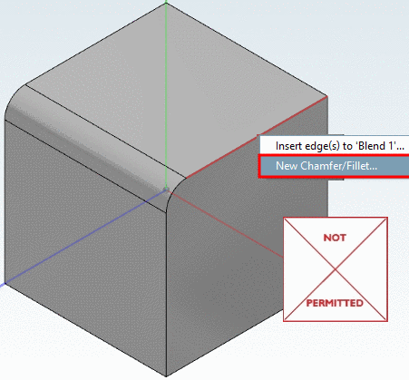
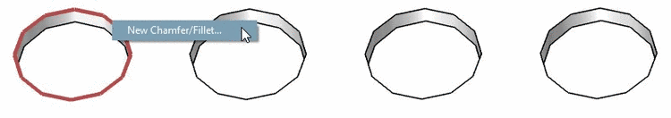
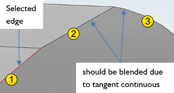
If subsequent edges have a connection angle < 15 degree, you just have to select one single edge in order to apply the function New Chamfer/Fillet... to all following edges as well.
![[Note]](/community/externals/manuals/%24%7Bb2b:MANUALPATH/images/note.png) |
Note |
|---|---|
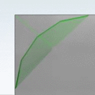
Tangent continuous may cause unwanted blends. In this case the blend has to be created earlier or by sketch. | |
For angles larger than 15 degree the tangent continuous does not take effect.
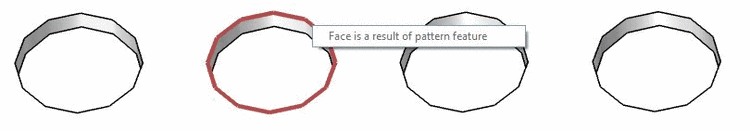
In following
example the first edge after the selected one is blended
 , the second one not
  (see figure under b), because the transition
angle is larger than 15 degree.
(see figure under b), because the transition
angle is larger than 15 degree.
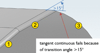
Real, PARTsolutions never depicts curves. Curves are always resolved in lines connected by a certain angle. If the resolution is too low, it may happen that the transition angle is larger than 15 degrees.
If a line follows a curve and tangent continuous fails, the problem is always too low resolution.

If a line follows a line connected by an obtuse angle and the tangent continuous fails, the reason is an angle of more than 15 degrees (see above).

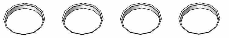
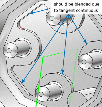
In following example edge selection is used. For a few edges tangent continuous works, but at two other edges tangent continuous stops due to too low resolution.

|
Note |
|---|---|
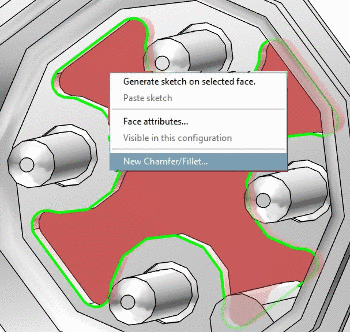
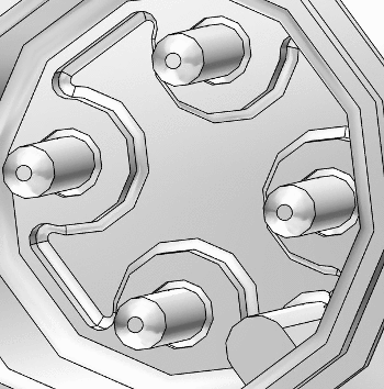
Especially for a continuous contour, do not use edge selection, but face selection, since this is considerably less effort compared to a selection of the individual edges! | |
The two following figures show the use of face selection.
|
Note |
|---|---|
| |
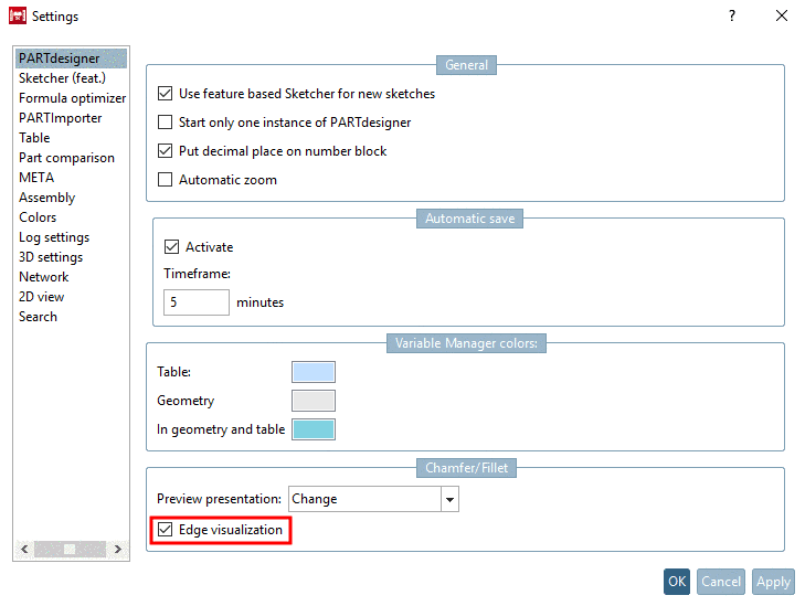
You can change the Preview presentation for Chamfer/Fillet in two ways:
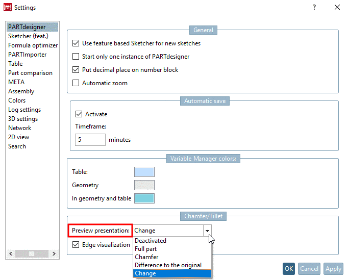


You can
activate/deactivate the Preview presentation in the Chamfer/Fillet
dialog  (see following figure).
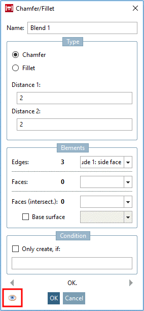
For Edge visualization the Preview presentation has to be activated. If Edge visualization is activated, you can see all edges where the Blend feature will be applied (see following figure).
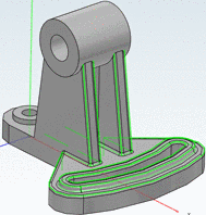
Editing mode with opened "Chamfer/Fillet" dialog box - All edges where the function shall be applied are marked in green.
You can change the settings for Edge visualization in two ways:
|
Note |
|---|---|
Just as well you can click on the eye symbol in the Chamfer/Fillet dialog box in order to activate or deactivate the Edge visualization (see Fig. „"Chamfer/Fillet" dialog box“). | |
In the following you can find examples for these three procedures:
-
Creation of ONE face with New Chamfer/Fillet.... Then in each further step, selection of only ONE face and using the command Insert face(s) to 'Blend xy'....
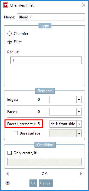
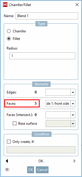
In the dialog box Chamfer/Fillet, under Faces, the total number of selected faces is shown. (At last step of repetition '5' in this example.)
All edges of individual faces are edited by the Blend feature (chamfer or fillet).
-
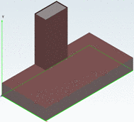
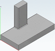
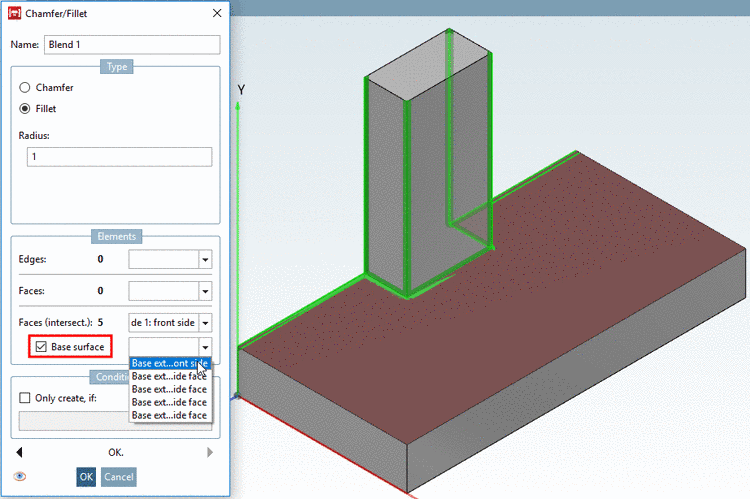
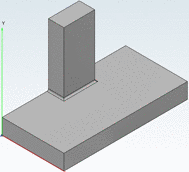
Selection of all faces in ONE step + definition of Base surface
Only edges adjoining the base surface are rounded (or bevelled). The vertical edges at the small cuboid for example are not rounded in compare to the use without base surface (compare above).


Once again all results in direct comparison:
-
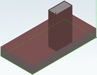
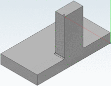
Selection of all faces in ONE step and then using command New Chamfer/Fillet...
-> The common cutting edges of all faces are rounded/bevelled.
-
Creation of ONE face with New Chamfer/Fillet.... Then in each further step, selection of only ONE face and using the command Insert face(s) to 'Blend xy'....
-> Edges of all selected faces are rounded/bevelled.
-
Selection of all faces in ONE step + definition of Base surface
-> Only edges adjoining the base surface are rounded/bevelled.
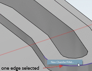
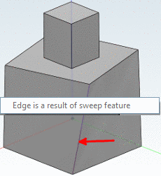
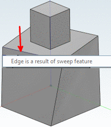
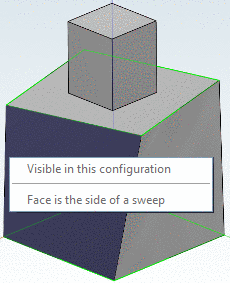
Face select: Blends are only allowed, when a non sweep surface is selected. If the face itself has attached surfaces which are sweeps the blend will work. Every other combination is not supported. So when one of the selected faces is a sweep face, the blend will fail (see Fig. „Sweep face cannot be blended“).
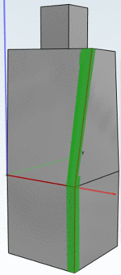
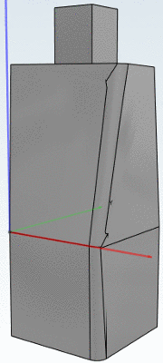
Edge select: The user must not select edges when one of the attached faces is a side face of a sweep (see Fig. „Edge between two sweep faces cannot be blended“ and Fig. „Edge between sweep and regular face cannot be blended“). Edges adjacent to front or back faces of a sweep are allowed (see Fig. „Blend on front face of sweep (selection)“ and Fig. „Blend on front face of sweep (result)“).
Face intersection: If one of the selected faces is a sweep face, the blend is not supported.
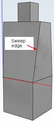
Tangent continuous: If we have to continue an edge tangentially and the resulting edge has faces with sweeps, it will fail (see Fig. „Sweep edge blended due to tangent continuous“). No error message is displayed, but the part will fail when exporting - depending on CAD system.