Manual
Login
Our 3D CAD supplier models have been moved to 3Dfindit.com, the new visual search engine for 3D CAD, CAE & BIM models.
You can log in there with your existing account of this site.
The content remains free of charge.

Top Links
Manual
 |
Modeling for the VDI field should ideally be performed with simple regular bodies[12], in order to ensure a correct export into the VDI format.
The following describes, with the help of examples, how bodies should be designed, meaning the number of features, feature types, etc.
In general terms: Bodies should be modeled as simple as possible.
Please note: VDI
export ONLY supports feature color, NO surface color. It is also essential
that in $CADENAS_USER,
in the configuration file debug.cfg, in the section
[PDESIGNER], there is a
key allowFeatureAttribueAll=1. If a
debug.cfg does not exist
yet, please create the file.
The following features should not arise in VDI models in any case:
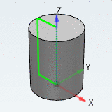
The simplest bodies are ball, cylinder and box. Modeling with these regular bodies results in an optimal output for VDI. They do not have an occurrence of "TRANS" or "ROTA" in their VDI code.
If something cannot be modeled with regular bodies, you can also use bodies which have "ROTA" (rotation) in their VDI code.
-
No occurrence of "TRAN" or "ROTA".
960;2;1;1Y;1_cube;bmp;Vorschau;
970;1;Cube 100 7;;QUAD;0;-50;-100;1;0;0;0;1;0;100;100;100;
970.02;1;G;QUAD;100;-50;0;-1;0;0;0;1;0;100;100;100;;;;;;;;1;
970.04;1;0.689999997615814;0.689999997615814;0.689999997615814;1;0.34499999880791;
0.34499999880791;0.34499999880791;1;1;1;1;1;20;0.0053906249813735;0.0053906249813735;
0.0053906249813735;1;
 -
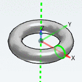
970;1;Torus 100-25 7;;QUAD;-12.5;-62.5000000000004;-12.5000000000002;1;0;0;0;1;0;125;
125.000000000001;25.0000000000003;
970.02;1;D;KREI;0;0;0;1;0;0;0;1;0;1;12.5;-50;0;
970.02;2;G;ROTA;50;0;0;1;0;0;0;0;-1;0;1;0;0;12.5;0;360;1;;;1;
970.04;1;0.689999997615814;0.689999997615814;0.689999997615814;1;0.34499999880791;
0.34499999880791;0.34499999880791;1;1;1;1;1;20;0.0053906249813735;0.0053906249813735;
0.0053906249813735;1;
In the following listing, different bodies are subdivided in the categories 1 to 4. Bodies from the categories 1 to 3 may be used. All not mentioned there fall under category 4 and may NOT be used.
-
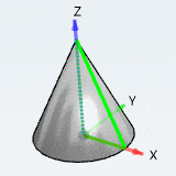
"Cone Rotated" based on a rotated triangle
(does not belong to the regular bodies of first order, however, also does not have "TRANS" or "ROTA" in VDI code)
-
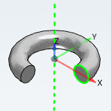
Once a bevelled rectangle is rotated, "ROTA" occurs in VDI code. A rotated circle also results in "ROTA" in code (Torus and Torus sector).
-
All bodies not mentioned above fall under category 4 and should NOT be used.
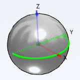
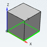
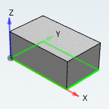
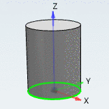

[12] "Regular bodies" are solids created on the base of very simple sketches such as semicircle, rectangle or circle, for example.
