Manual
Login
Our 3D CAD supplier models have been moved to 3Dfindit.com, the new visual search engine for 3D CAD, CAE & BIM models.
You can log in there with your existing account of this site.
The content remains free of charge.

Top Links
Manual
 |
-
Switch into the configuration mode in PARTdataManager and check which rule is the connection between the moveable parts – e.g. cylinder and piston. Open the rule then.
-
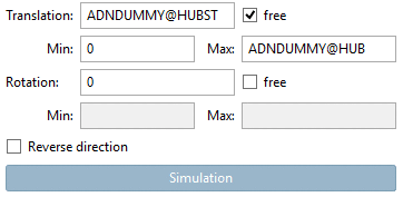
In the dialog area Positioning, the checkbox Translation „free“ must be activated and the Min. and Max. values must be specified according to the physical limits of the “real” product. (In the example in hand it's about a Translation movement of the piston.)
-
-> The dialog box Simulation attributes is opened.
-
-> The dialog box Class selection is opened.
-
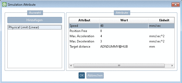
Choose Actuator > Actuator Linear > Physical Limit (Linear) and confirm with .
-> The respective attribute is displayed in the dialog box.
-
Determine the values of the attributes according to the real product.
In the context menu of an opened field you can find different helpful functions.
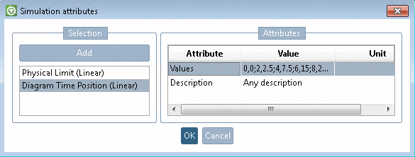
Optionally, motion profiles can be set up, in order to perform a dynamic movement (e.g. given by motion diagrams in the original product data). In this case click again and choose Actuator > Actuator Linear > Diagram Time Position.
Then determine the values according to the following pattern. (Any number of pairs is possible.)
Time,Position;Time,Position;etc.
0,0;2,2.5;4,7.5;6,15;8,25;10,40
It is also possible to add several motion profiles, e.g. if you have different diagrams for different loads. You can use them separated also later in the MCD. In order to differ them from each other, you can add a.Description in the window.
The part is ready for export and testing now. See below.


![[Note]](/community/externals/manuals/%24%7Bb2b:MANUALPATH/images/note.png)