Manual
Login
Our 3D CAD supplier models have been moved to 3Dfindit.com, the new visual search engine for 3D CAD, CAE & BIM models.
You can log in there with your existing account of this site.
The content remains free of charge.

Top Links
Manual
 |
In the following a small example is given how to insert a connection:
-
Call up under PARTsolutions menu -> Connection
-
Select a hole type. Here exemplarily clearance hole.
-
Select the appropriate reference elements (edges) for the calculation of the components' thickness and confirm with .
-
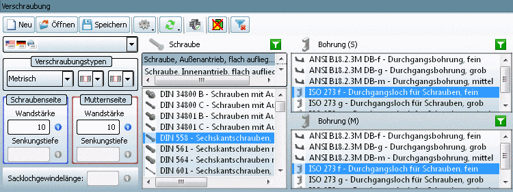
The view returns to PARTdataManager. Select the desired connection and determine whether you want to transfer the connection with
 or without
  hole.
hole.The following figure shows the selection of a hexagon bolt and the selection of the hole ISO 273f on bolt and nut side.
-
The view returns to the CAD system.
Select the desired placement method. Here exemplarily On surface
 .
. -
The ProE Selection dialog box is displayed.
Click on the desired insertion point on the surface and confirm with .
-
Optionally the ProE Menu Manager with the section "Create holes?" is displayed - if under PARTdataManager -> Connection section the option "Transfer with hole"
had been selected. -


A detailed description of the Connection section is found under Section 3.1.1.10.4, “User interface in detail ”.
