Manual
Login
Our 3D CAD supplier models have been moved to 3Dfindit.com, the new visual search engine for 3D CAD, CAE & BIM models.
You can log in there with your existing account of this site.
The content remains free of charge.

Top Links
Manual
 |
In a last step the cap nut gets an inner thread.
-
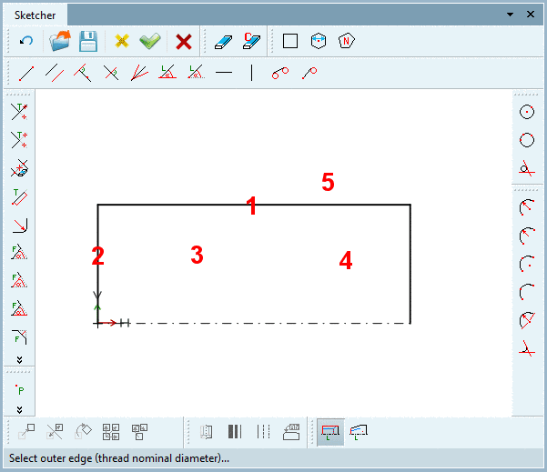
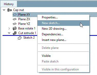
With the secondary mouse key, call the context menu of Plane XY.
Lead the cursor to the KO zero-point until the snap appears and fix it with a mouse click.
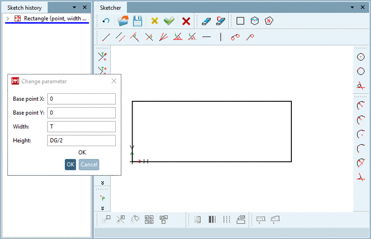
From the KO zero-point draw the rectangle and fix it with a mouse click.
-
In the dialog box Change parameter enter T as width, DG/2 as hight and confirm with .
-
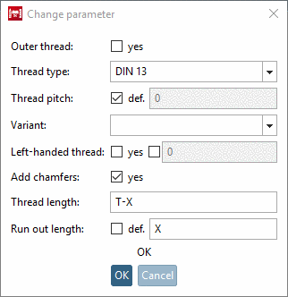
Click the button Cylindrical thread by length
 .
.Click on the respective sketch elements and areas and follow the notes in the footer:
The Change parameter window opens.
Insert 'T-X' for the Thread length and 'X' for the Run out length.
Confirm with . --> The thread is created.
-
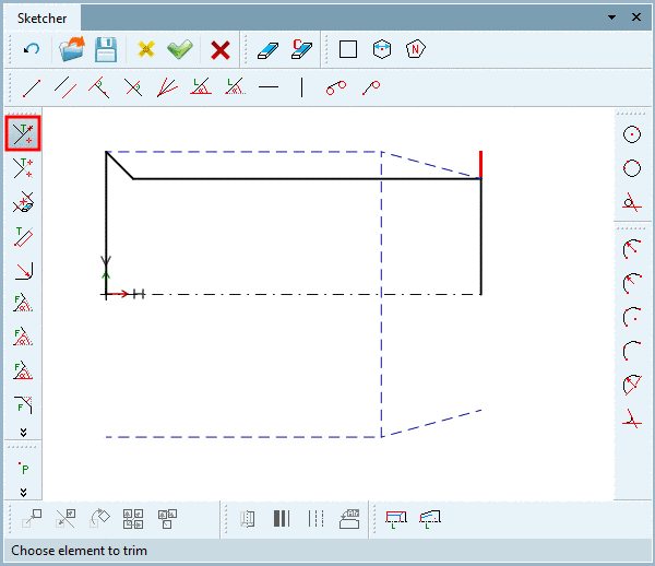
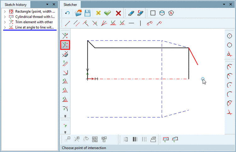
Trim the overhanging line end.
On this, click on the button Trim element with other
 . Choose the element to be trimmed and then the
desired intersection point.
. Choose the element to be trimmed and then the
desired intersection point. -
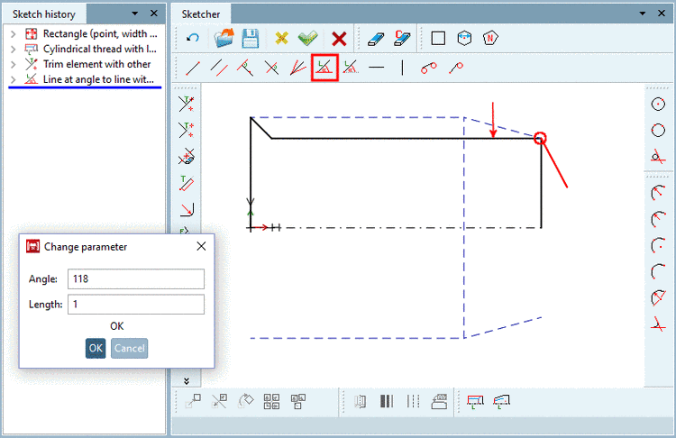
Add a line at angle of 118°+180° with length 1.
Hereto click on the button Line at angle to line with length
 .
.Select the Base line and the Start point. --> The new line follows the cursor.
Choose the rough position and confirm with a click. --> The dialog box Change parameter is opened.
-
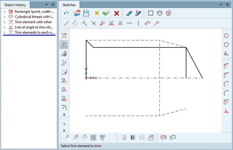
Trim the marked elements to each other in their intersection point.
Click on the button Trim elements to each other
 .
.Select the first element to be trimmed, then the second and then the desired intersection point.
Result:
-
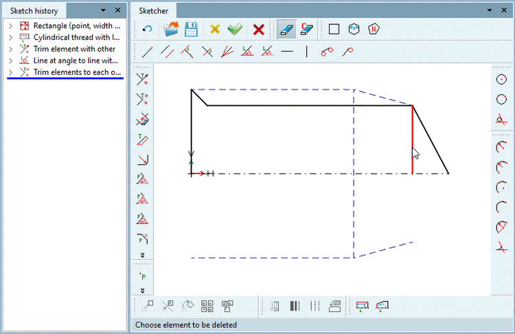
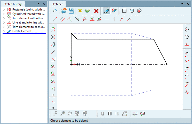
Hereto click on Delete Element
 .
.Delete the line which is highlighted in red in the following figure.
-
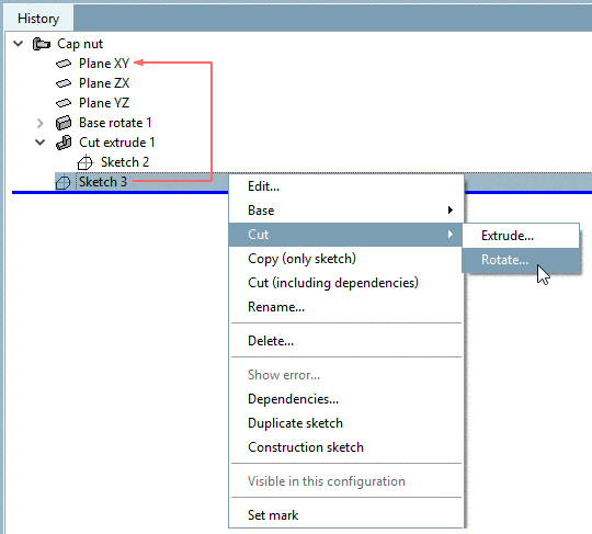
In the context menu of Sketch 3, select Cut -> Rotate....
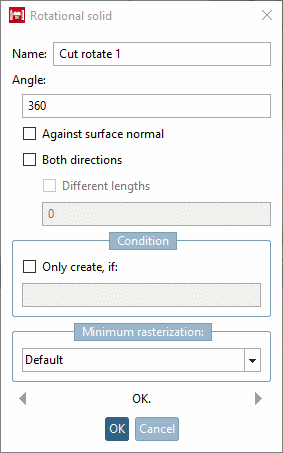
--> The dialog box Rotational solid is opened.
-
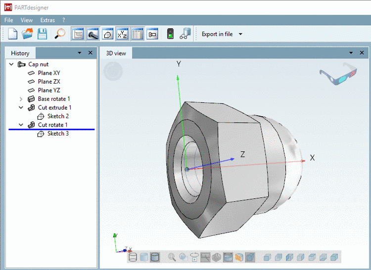
Leave the defaults and confirm with .
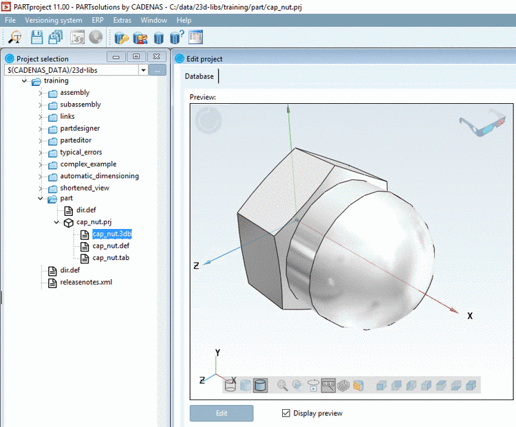
--> The finished cap nut is displayed in the 3D view.

![[Note]](/community/externals/manuals/%24%7Bb2b:MANUALPATH/images/note.png)