Manual
Login
Our 3D CAD supplier models have been moved to 3Dfindit.com, the new visual search engine for 3D CAD, CAE & BIM models.
You can log in there with your existing account of this site.
The content remains free of charge.

Top Links
Manual
 |
The parts created in PARTdesigner can be configured to assemblies with the Configurator.[41]In order for this to happen, the parts in PARTdesigner must be assigned precisely defined and named insertion and connection points .
|
A cuboid contains a boring into which a screw is to be inserted later (assembly configuration). Therefore a connection point needs to be applied for the boring. |

Click on the Face, in which the boring is to be applied. --> The according Sketch shows up in the History highlighted in color.
-
Right-click on the context menu of the sketch (in this example, Sketch 2).
-
"Catch" the center of the circle (boring) with your cursor and affix it with a simple mouse-click.
--> The point gets a green triangle symbol .
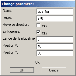
--> The Change parameter window opens.
Assign a name to the connection point - for example: CP1 - and confirm with .
Optionally, you may make changes in the other fields as well.


The name conventions is to be explained in detail using the example of a profile:

A connection point is needed in the center of the section and one in each hole. Compare Fig. „3 connection points each at start and end, 8 insertion lines at the ducts“.
The connection point in the center of the section is called start, the others are listed as start_a, start_b etc.
The same counts for the profile end.


Sideway connection points (insertion lines)
![[Note]](/community/externals/manuals/%24%7Bb2b:MANUALPATH/images/note.png) |
Note |
|---|---|
|
The sideways Connection points are created as Connection line. See Section 7.5.4.3.2.1.6, “Create Connection line ”.
| |

The following image is an example of the name convention for the insertion lines on the side. Your basic sketch is located on the start plane of the profile.
![[Important]](/community/externals/manuals/%24%7Bb2b:MANUALPATH/images/important.png)


Example of a complex name convention with many connection points and insertion lines and different proportions
The start/end connection points/insertion lines are now a letter combination of top/side and or bottom/side:


The connection points must be created in such a manner that the connection parts have the same direction. This means that a connection element may not be turned 180° because then the open side of the cable duct must always be on the same side.
This is reached because the red axis always points upwards.
The following figure shows two parts that need to be connected:
|
|
|
Result: The red axes are on top of each other, the green and blue axes point in the opposite direction
|


In order for the fences to be able to move around the hinge, the connection points must be in opposite directions.
In this example, the red coordinate axes are also on top of each other, so the respective connection point of the right and left fence must be opposite each other.
One connection point points upwards, the other downwards.
One of the red axes of the coordinate system points out of the fence, the other into it.


The creation of the "End" connection point occurs in the same way as described above.
The following examples show what should be noted for connection points at connection elements.

|
Note |
|---|---|
|
Rule of thumb: Number, position, orientation and naming (numbering) of insertion points must be noted! Number, position and naming results from the PCon classification. | |


Connection lines can be used for movable elements. For example, for connectors of profiles, which move in a groove.
Connection lines are created from a combination of one "normal" connection point and an absolute plane.
Create connection point (line)
|
Open a new sketch and enter the desired connection points.
|
|
|
Connection lines are identified by pyramid symbol and additionally with a green line at the pyramid's base. |
|
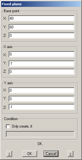
Create absolute plane in connection with connection points
|
Every Connection point needs its Fixed plane. The Base point indicates the starting point of a Connection line.
|
|

Name convention plane - connection line
The name of the plane must be plane_<side_nr>.
In other words: The numerical value of a plane corresponds to the numerical value of the respective connection point (connection line):
plane_1 <-> side_1, plane_5a <-> side_5a, etc.
The sum of the numerical values of the opposite connection points must be the same. (In this example: 1+6, 2+5, the sum is 7 both times).

