Manual
Login
Our 3D CAD supplier models have been moved to 3Dfindit.com, the new visual search engine for 3D CAD, CAE & BIM models.
You can log in there with your existing account of this site.
The content remains free of charge.

Top Links
Manual
 |
In the following a hand wheel is drawn and all needed steps explained in detail:
-
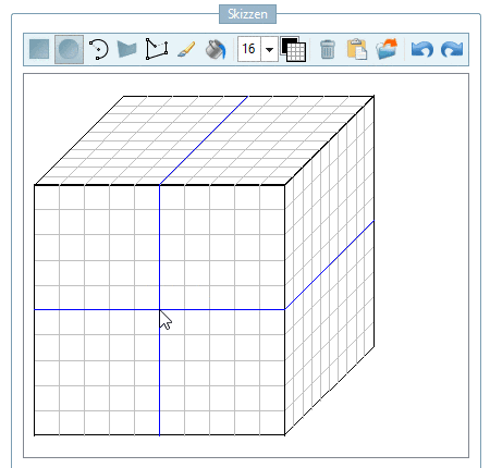
Draw the first view on the front cube face. When clicking on another cube face, you can turn it in the foreground anytime and then edit.
-
-
-
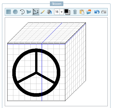
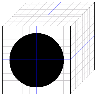
With the left mouse key, click on the center of the drawing and with held Ctrl key, draw a black circle.
-
Click on Choose erasing color.
-
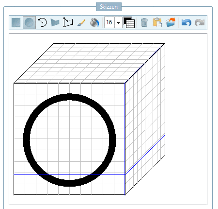
With the left mouse key, click into the center of the drawing again. Once you are close to a snap point it displays.
Click on the snap point and with held Ctrl key, draw a smaller white circle.
-
Once again click Choose color for painting.
-
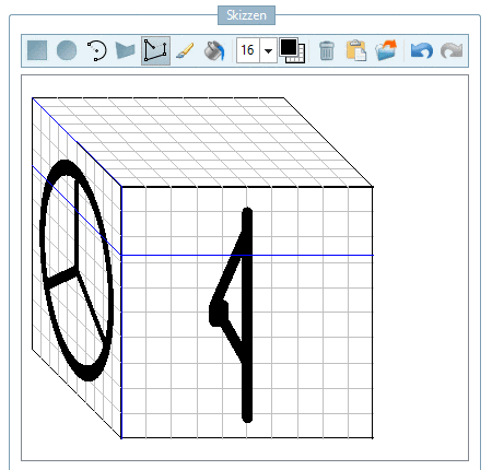
Click on the icon Draw polygon chain.
-
-
-
-> The view turns in the foreground. Now draw the second sketch view. The needed option is already selected.
-
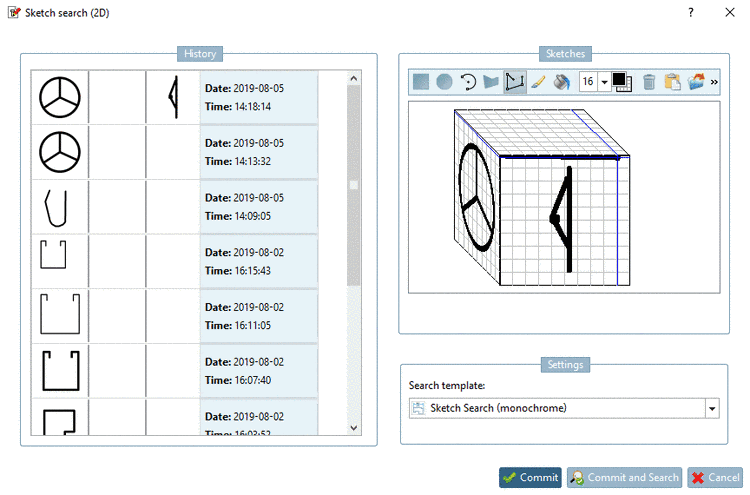
Close the Sketch search (2D) dialog box with
 , or
, or
 .
. -
Settings: In this example, select the Search template "Search by Sketch (monochrome)".
-
-> The search results are listed below.
Optionally, you can load parts into the Part comparison now. When you move the mouse cursor over a line, different icons will be shown:
You can find detailed information on Part comparison under Section 3.1.6.10, “ Part comparison ”.


![[Note]](/community/externals/manuals/%24%7Bb2b:MANUALPATH/images/note.png)