Manual
Login
Our 3D CAD supplier models have been moved to 3Dfindit.com, the new visual search engine for 3D CAD, CAE & BIM models.
You can log in there with your existing account of this site.
The content remains free of charge.

Top Links
Manual
 |
You want to place a profile rail of a series of borings with the same distance.

Step 1: Set a boring, which is to be used as the pattern for the others.

Rotate the created contour via Cut rotation .

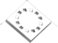
-> Intermediate result: The hole pattern has been inserted.


The creation of a rotated pattern corresponds to the method of creating a pattern with equal orientation (see above).

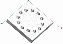
The starting basis for the following commentary is a boring that is to be duplicated 12 times.

-
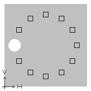
Via the button Choose new pattern origin... set the pattern origin on the desired boring.
-
Via Generate sketch on selected face. set a new sketch for the pattern.
-
In this sketch, set the point of origin for the construction of the pattern at the same place as the point of origin in the other sketch is located.
-
While holding down the CTRL button, select the button Rotate selection .
-
Adjust the values in the input fields Number, Rotation point and Angle of rotation and confirm with .
-
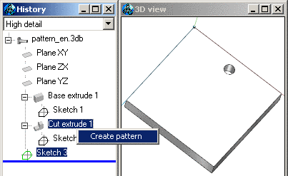
In the History mark Cut extrude and the sketch, which contains the pattern (in this example Sketch 3) and in the context menu, click Create pattern .
--> The borings are multiplied according to the pattern.


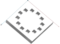
In the sketch, delete the circle and replace it with a square.

The bore holes are now arranged in squares and circles (but still equally oriented).


Taking over patterns into the CAD system may be problematic. In ??? a warning may be issued for certain cases.
![[Note]](/community/externals/manuals/%24%7Bb2b:MANUALPATH/images/note.png) |
Note |
|---|---|
|
The following cases must be differentiated between:
| |
| Linear pattern with 13*2=26 elements with 2 empty spaces | Linear pattern with13*2=26 elements with 8 empty spaces | Linear pattern with 6*2=12 elements with 7 empty spaces |
| OK | Warning | OK |


