Manual
Login
Our 3D CAD supplier models have been moved to 3Dfindit.com, the new visual search engine for 3D CAD, CAE & BIM models.
You can log in there with your existing account of this site.
The content remains free of charge.

Top Links
Manual
 |
Frames are parts which can receive a set of sub-connectors. With the help of them specifically defined connectors can be assembled. The inserts are often named as plug-in modules. Beyond that frames have no great electrical functionality. The most important point when using frames are the mounting points (places where plug-in modules can be inserted). On this also see Section 5.13.10.5, “Classify Mounting Points (Mounting Point [CNS_CP|4|6] and Mounting Description [CNS_CP|4|7])”.
In the case of frames, slots have a special additional meaning. They do not only determine the position of the plug-in module, but also describe a virtual "connection". This is an electrical connection which does not appear in the model itself.
This is also the reason why they are classified in the main category "Connectors".
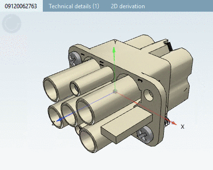
Following figure shows a plug-in module, which can be received by a frame.
Mounting Descriptions are modelled completely analogously to all other electrical parts in the described manner.
Following figure shows a frame which can be plugged into connection points classified as Mounting Point with attribute Description and value "HOOD_HOUSING" and can receive 3 connectors with connection points classified as Mounting Description with attribute Description and value "MODULE_A" to "MODULE_C".
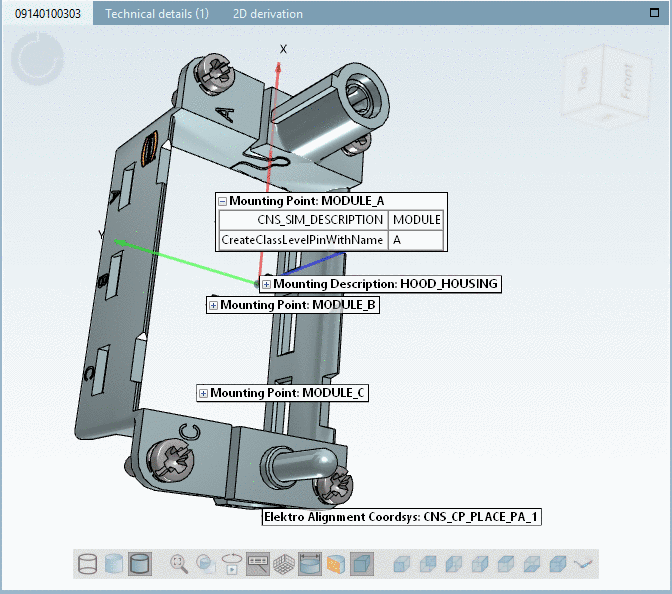
Label in the 3D view in PARTdataManager: <Class name> (here Mounting Point):<Value of attribute "Description">
Label in the 3D view in PARTproject: <Class name> (here Mounting Point):<Value of attribute "Description">
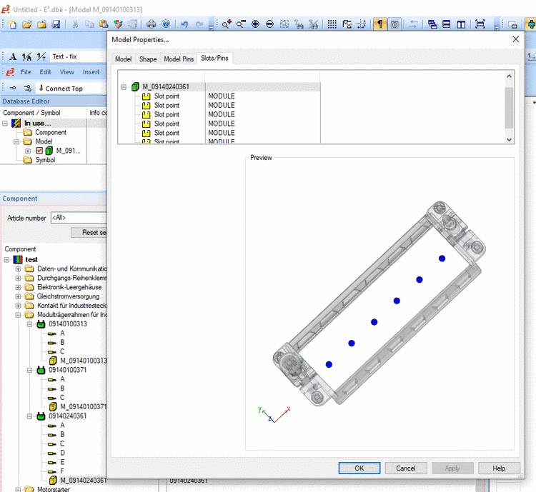
Frame with 6 Mounting Points (description respectively "MODULE"). The dialog Model Properties shows typical slots (MODULE), where connectors (see Fig. „Plug-in module“) can be plugged into such a frame.
Virtual connections (dummy lines) are set in the class CNS_CP|4|6 with the attribute CreateClassLevelPinWithName=Pinname. If this attribute is set, interfaces will also create respective virtual connections (dummy lines) beside the mounting points. Display name in an ECAD system (e.g. Zuken E3) is the value of the attribute "CreateClassLevelPinWithName".
Virtual connections (dummy lines) do not contain geometry, but are implicitly linked with the respective mounting point; the only property is the name (here "A" to "C").
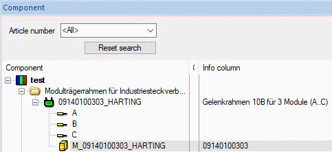
Harting part 09140100303 in E3: Frame with 3 virtual connections with A, B and C. The 3 respective slots have the description "MODULE" (compare above).
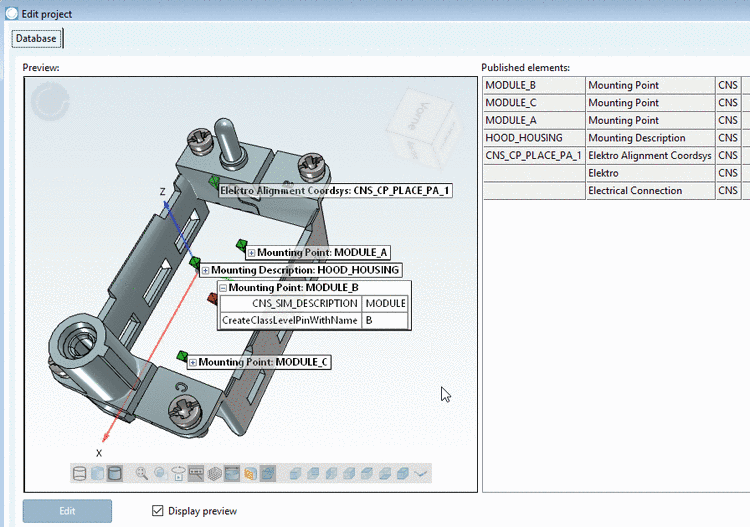
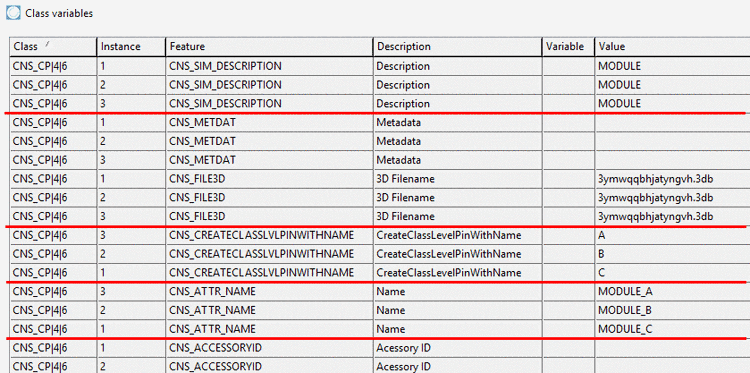
Classification of the frame from above figure in PARTsolutions. Here, "CNS_SIM_DESCRIPTION" describes the slot description, whereas the optional attribute "CreateClassLevelPinWithName" causes the system to create a virtual connection with respective name (here A) beside the slot. This attribute should be used exclusively.
