Manual
Login
Our 3D CAD supplier models have been moved to 3Dfindit.com, the new visual search engine for 3D CAD, CAE & BIM models.
You can log in there with your existing account of this site.
The content remains free of charge.

Top Links
Manual
 |
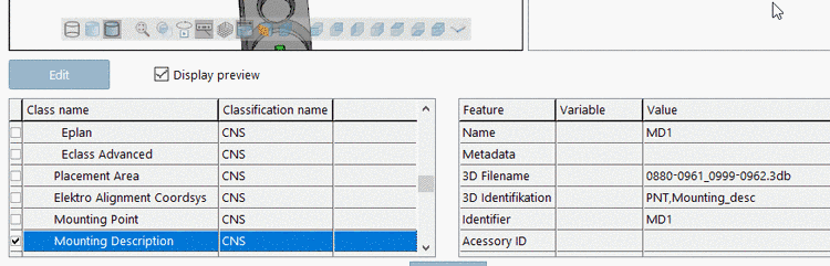
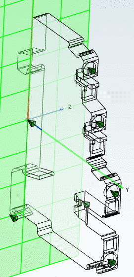
Mounting Point describes at which places of the component other components can be mounted.
Mounting Description describes point and direction where the part itself can be plugged into a compatible component (DIN rail, directly on the plate, etc.). For this reason the connection point has to be correctly positioned, otherwise the device will get a wrong orientation.
![[Note]](/community/externals/manuals/%24%7Bb2b:MANUALPATH/images/note.png)
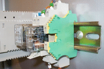
For rails the following must be observed:
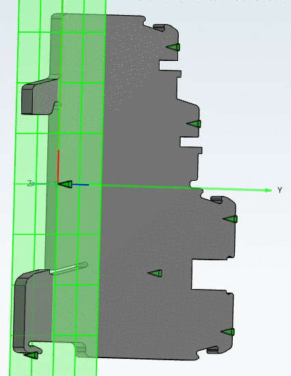
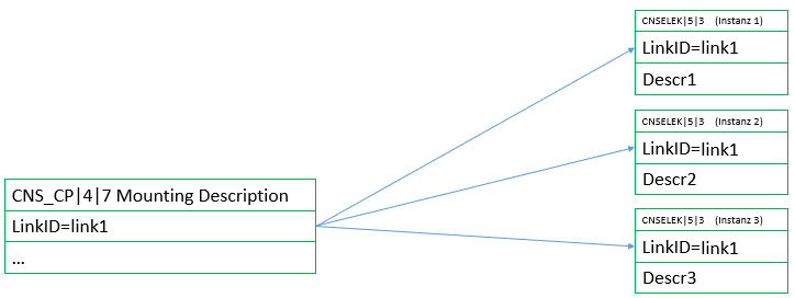
In the following setting a Mounting Description is described:
-
Classify the connection point as Mounting Description (CNS_CP|4|7). (Preferably a connection point had been created especially for this purpose.)
-
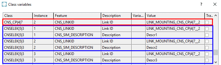
In particular, enter a value for the attribute Link ID.
-
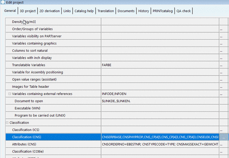
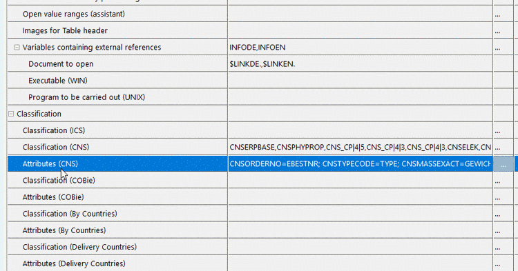
Save the progress and in PARTproject, change to the tabbed page General.
Here, open the Classification (CNS).
-
In the Filter, set the option Classes and under Elektro -> Auxiliary, via double-click on the class Mounting Description (CNSELEK|5|3), add the needed number of appropriate instances (1,2,3,4,...).
-
-
In the attribute Link ID, enter the same value which you entered before in the class Mounting Description (CNS_CP|4|7).
Under Description, enter the specific name which has to match the respective value under Mounting Point -> Description.
Here in this example the value TS35 is the Mounting Type of the device (TS35 = DIN rail 35mm).