Manual
Login
Our 3D CAD supplier models have been moved to 3Dfindit.com, the new visual search engine for 3D CAD, CAE & BIM models.
You can log in there with your existing account of this site.
The content remains free of charge.

Top Links
Manual
 |
In the following you can see how to classify a Sensor and to check the classification in the Mechatronics Concept Designer.
![[Note]](/community/externals/manuals/%24%7Bb2b:MANUALPATH/images/note.png) |
Note |
|---|---|
|
Precondition is a current CNS classification. Install it in PARTadmin under Catalog update -> Online -> selection Classifications.
| |

-
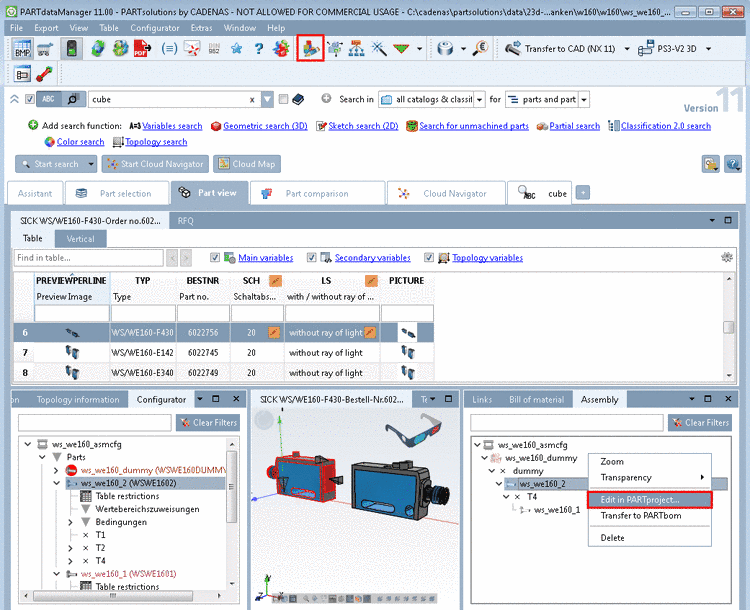
In the Configurator, select the part to be classified in the assembly and open it via context menu command in PARTproject.
-
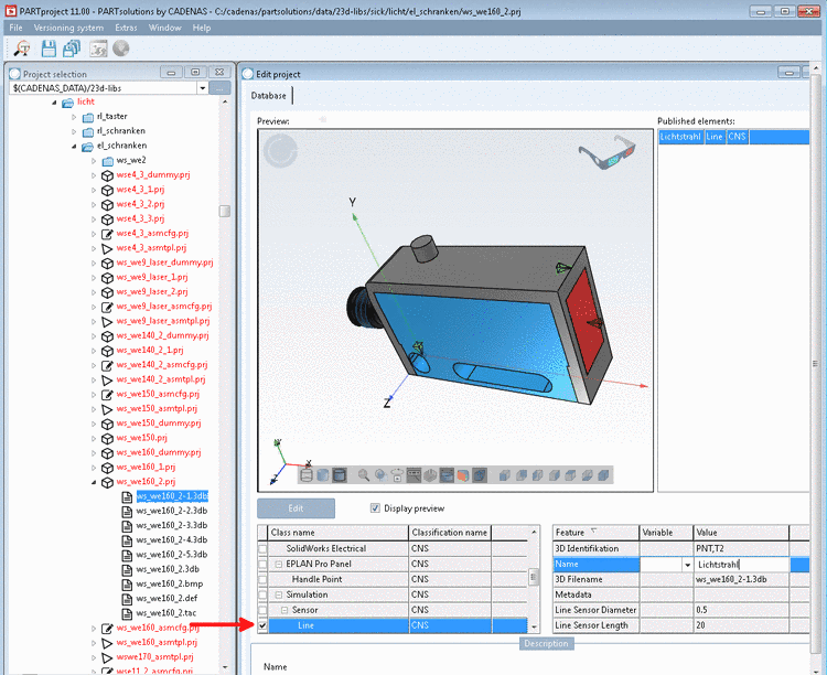
Under Project selection, select the 3db file.
-> On the right under Edit project, a Preview is displayed.
-
On the feature to be classified (here a connection point), call the context menu command Choose connection point.
-
In the case of a sensor, select the class under Simulation -> Sensor -> Line.
-> Beside the selected class the single attributes are displayed.
In the case of a sensor, please set the following values:
-
Line Sensor Length: Length of light ray
-
Scroll down in order to see this attribute.
Value range: 0,1,2 (0 for X, 1 for Y and 2 for Z)
For the classification of the light ray a connection point is used. The light ray has to be co-directional to the model's coordinate system. However, connection points have their own orientation (their own coordinate system).
In order to detect the correct attribute value, proceed as follows:
-
At the coordinate system of connection point, detect the color of that axis, which is co-directional to the axis of the model's coordinate system.
-
Detect, which is the blue axis in the model's coordinate system.
For the attribute value of Length axis, set the value 2 (see help text under "Description").
-
The values for 3D identification and 3D Filename are automatically set. Metadata may remain empty.
-
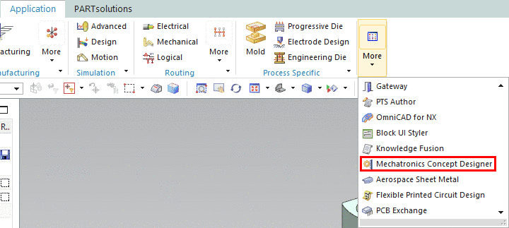
In NX under Application -> More open Mechatronics Concept Designer.
-
-> Under Sensors and Actuators you can see the classified connection point.
-
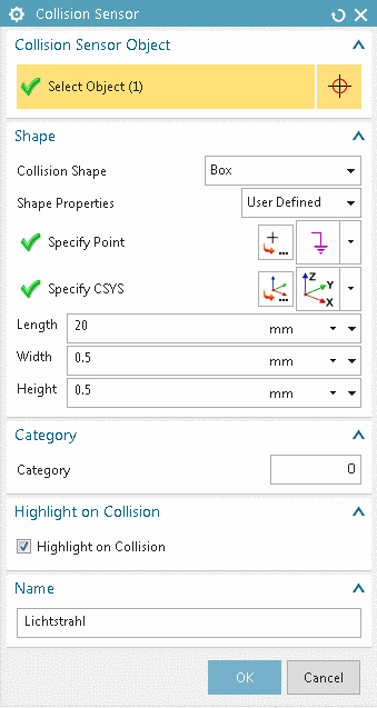
In the context menu, click on Edit.
-> The dialog box Collision Sensor is opened.
You see, Length, Width, Height and Name have been transferred from the classification.