Manual
Login
Our 3D CAD supplier models have been moved to 3Dfindit.com, the new visual search engine for 3D CAD, CAE & BIM models.
You can log in there with your existing account of this site.
The content remains free of charge.

Top Links
Manual
 |
In many situations it is necessary to model connections between different classification entities. This happens in a very general form by using the class Inter Part Link. It allows first to create completely abstract connections and is not restricted to a part. For example, this could be a switch cabinet with different terminals, which are connected by cables. In this example, the connection information describes the physical cabling in an abstract way as logical connection.
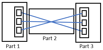
Schematic depiction of a sensor cable (plug - cable - plug) - In general both the two plugs and the cable will be separate projects. The system is not restricted in this respect.
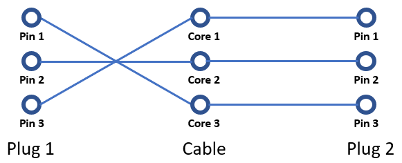
The schematic depiction from above graphic is not advantageously for our purposes. So we will consider the example in a logical depiction (analogously to circuits).
In this logical depiction individual properties like length, size, width, weight are irrelevant. In this context the only decisive is the connection information as following figure illustrates.
In the highest level of abstraction the situation can be reduced to following table:
| Pin in part 1 | Connection to core (left side) | Connection from core (right side) | Pin in part 2 | |
| 1 | 1 | Cable | 1 | 3 |
| 2 | 2 | 2 | 2 | |
| 3 | 3 | 3 | 1 |
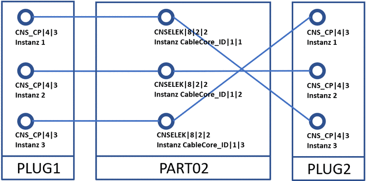
On this level, the CNS class CNSELEK|5|7 (Inter Part Links) is working. This class enables to build connections between general class instances (two nodes [vertex]) on an abstract level. Please regard that in above example the single pins are instances of the class CNS_CP|4|3 (electrical connection); the cable cores are instances of the class CNSELEK|8|2|2 (cable core). Because of this above table has 6 connections. That means, a connection from the pins of part 1 on the left side to the core's left side and from the core's right side to the pins of part 2.
The information to which parts a single class instance belongs is given through "aliases" (unique identifiers). You can see it in PARTdataManager, in the dialog Assembly structure, for example.
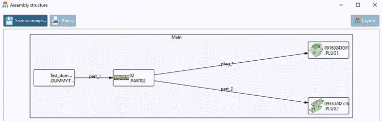
In example case applies: Part 1 has the alias "PLUG1", the cable the alias "PART02" and the second plug alias "PLUG2". With these "ingredients" we can model this situation.
The class CNSELEK|5|7 (Inter Part Link) has the following features:
Vertex 1 ASM Member ID: Localizes the part (1) of the outgoing connection via respective alias.
Vertex 1 Class Instance: Localizes the corresponding class instance in part (1)
Vertex 2 ASM Member ID: Localizes the part (2) of the incoming connection via respective alias.
Vertex 2 Class Instance: Localizes the corresponding class instance in part (2)

For the features Vertex Class Instance and Vertex Asm Member ID, a concept analogous to XML X-Path is used (here, the pipe symbol instead of "/"). Once in order to localize the part in assembly and then in order to determine the respective class instance in part. The only important point is that the root object (assembly) is localized via the implicit alias "root". Above table data takes the following form:
Eight rows describe a complete connection of a pin in plug 1 with a pin in plug 2 via cable core.
The presented schema is not restricted to systems like plug-cable-plug, but can describe any connections between class instances in different parts. The meaning of such constructs depends on the special case and is not determined by the class Inter Part Links initially.
Note: For example, it is also possible to connect a class instance "living" on the assembly itself with a class instance of a part. This would look as follows:
Subcircuits directly follow the above described general procedure. However, in order to explicitly create a subcircuit, on assembly level, the class CNSELEK|1 has still to be written with the feature Override Component Type, with the value "SubCircuit". This requires a consistent modelling of the Inter Part Links.

