Manual
Login
Our 3D CAD supplier models have been moved to 3Dfindit.com, the new visual search engine for 3D CAD, CAE & BIM models.
You can log in there with your existing account of this site.
The content remains free of charge.

Top Links
Manual
 |
Now the rules will be defined which result in the correct creation of an assembly.
On the
connection point ( ) of the dummy part (base_dummy) the
Connection part "wing_1" is
connected via a Rule
to the Connection point "mitte".
) of the dummy part (base_dummy) the
Connection part "wing_1" is
connected via a Rule
to the Connection point "mitte".
-
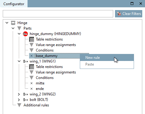
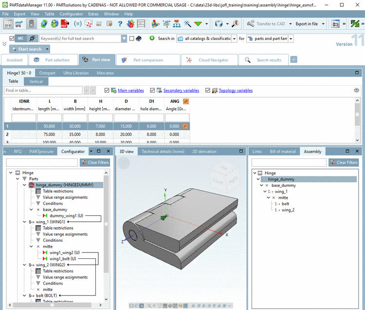
Call the command New rule on connection point "base_dummy".
-
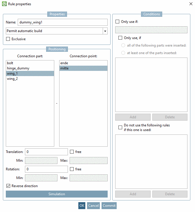
Under Connection part, select "wing_1" and under Connection point, select "mitte".
Better do not activate the option Exclusive, except you are quite sure that the connection point will be used be only one part.
Possibly, activate the option Reverse direction, in order to correctly position a part. (In the case of the connection between base_dummy and "wing_1" it is correct, to bring wing_1 into the correct position.)
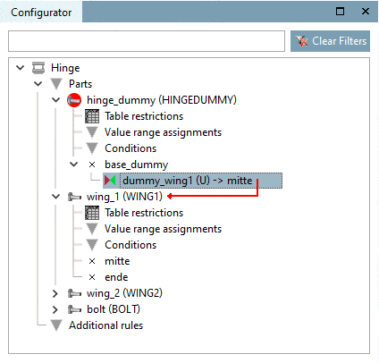
-> The relation between "base_dummy" and connection point "wing_1" is signalized by an arrow line.
-
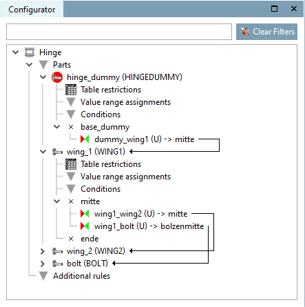
Now connect wing_1 with wing_2 and bolt or alternatively wing_2 with bolts via further rules.
After all connections are established, the following picture results.
-
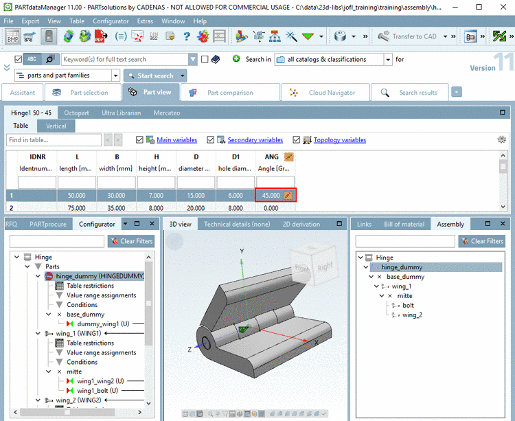
In the docking window Assembly, now build up the configuration by alternating selecting parts in the listing and selecting table rows.
-
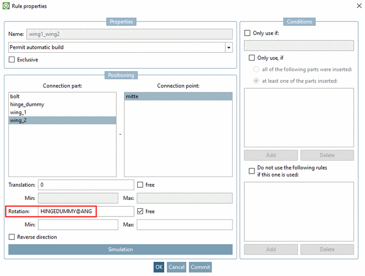
In order to be able to variably control the angularity, do the following:
At wing_1, call the dialog box Rule properties via context menu of connection point (
).
Put the following entry in the area Positioning in the field Rotation:
HINGEDUMMY@ANG
The variable "ANG" takes place in the dummy part which will not be exported but the table of the dummy part will be used by the assembly table project. The control of the angularity occurs this way in the assembly.
Now you can control the opening angle of the hinge with the value range variable "ANG".
-
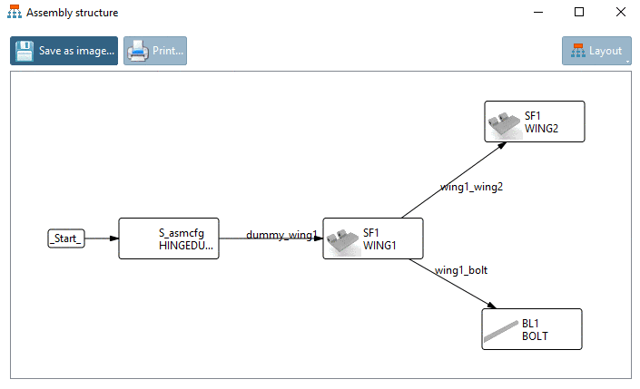
When opening the assembly configuration in PARTdataManager and then clicking the button Show assembly structure
 , you can see how parts are connected by rules
in a graphic.
, you can see how parts are connected by rules
in a graphic.
![[Note]](/community/externals/manuals/%24%7Bb2b:MANUALPATH/images/note.png)
