Manual
Login
Our 3D CAD supplier models have been moved to 3Dfindit.com, the new visual search engine for 3D CAD, CAE & BIM models.
You can log in there with your existing account of this site.
The content remains free of charge.

Top Links
Manual
 |
Because the model in the project does not necessarily have the correct orientation for the ECAD programs, it must be rotated manually.
This is achieved by placing a connection point (that will act as the origin point of the new coordinate system) in the 3db and by classifying it as Elektro Alignment Coordsys.
The way the device is mounted (in real life) defines the orientation and position of the connection point.
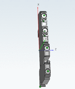
The orientation in the 3db clearly doesn't match the orientation needed for ECAD programs.
The device rotation is done in the following manner:
![[Note]](/community/externals/manuals/%24%7Bb2b:MANUALPATH/images/note.png) |
Note |
|---|---|
Currently the procedure described in the following has to be done manually; a Wizard for work simplification is under work. | |
-
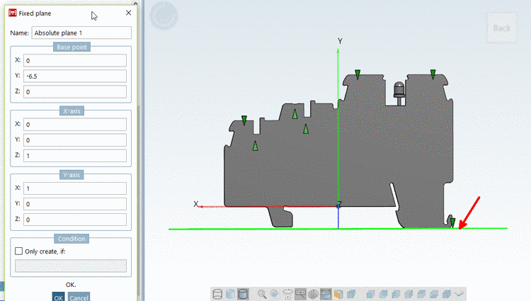
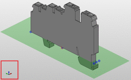
Right click on the model, and choose Insert Fixed plane....
-
Position the plane on the bottom (which will be the mounting surface later in ECAD), so that the outmost point (mostly several) of the part is touching the plane, meaning the part will not cut the plane, meaning the respective side of the bounding box matches the plane.
-
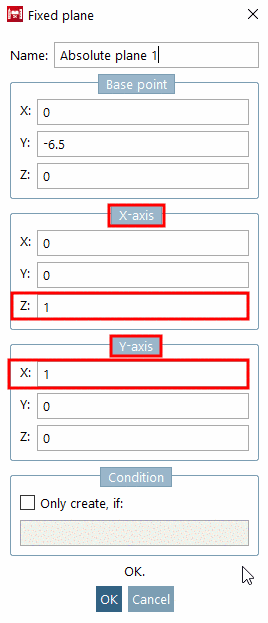
Now you need to define the orientation of the plane according to the observations made in the steps above.
-
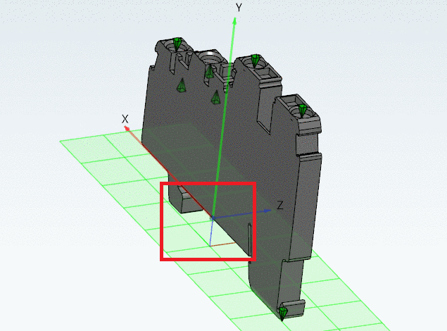
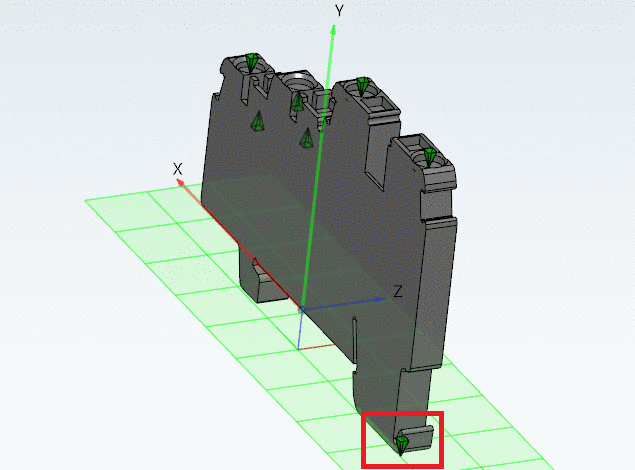
Place a connection point on the already positioned plane.
The point should be at the bottom left of the device, respectively to its mounting orientation. The top of the connection point is showing the direction of the negative Z axis (of the new coordinate system).
-
Classify the connection point that will be used as the orientation point as Elektro Alignment Coordsys. The name, identifier.... are filled out similarly to those of the electrical connection points.