Manual
Login
Our 3D CAD supplier models have been moved to 3Dfindit.com, the new visual search engine for 3D CAD, CAE & BIM models.
You can log in there with your existing account of this site.
The content remains free of charge.

Top Links
Manual
 |
![[Note]](/community/externals/manuals/%24%7Bb2b:MANUALPATH/images/note.png) |
Note |
|---|---|
Precondition to
be able to use this function and for the context menu command to be
displayed is that the files | |
|
Note |
|---|---|
The Connection Point Wizard can ideally be used in combination with the plugin Electrical classification import/export. | |
With the help of
the Connection Point
Wizard, via the functions  Create Cp (Ctrl+C)
(for a single feature),
Create Cp (Ctrl+C)
(for a single feature),  Create Cp (All) (Ctrl+A) (for all identical features) or
  Save as template (Ctrl+S), you can automatically set connection points on
features.
Save as template (Ctrl+S), you can automatically set connection points on
features.
Furthermore, via
the functions  Create BoundingBox Cp (Ctrl+B) and
  Save BBox as template, you have the possibility to place a connection point on
a corner of the BoundingBox. On this also see Section 5.13.10.1, “Align
component”.
Save BBox as template, you have the possibility to place a connection point on
a corner of the BoundingBox. On this also see Section 5.13.10.1, “Align
component”.
In the following, first the basic setting options will be explained. Then two examples follow, one to explain setting of connection points on features, one on the BoundingBox.
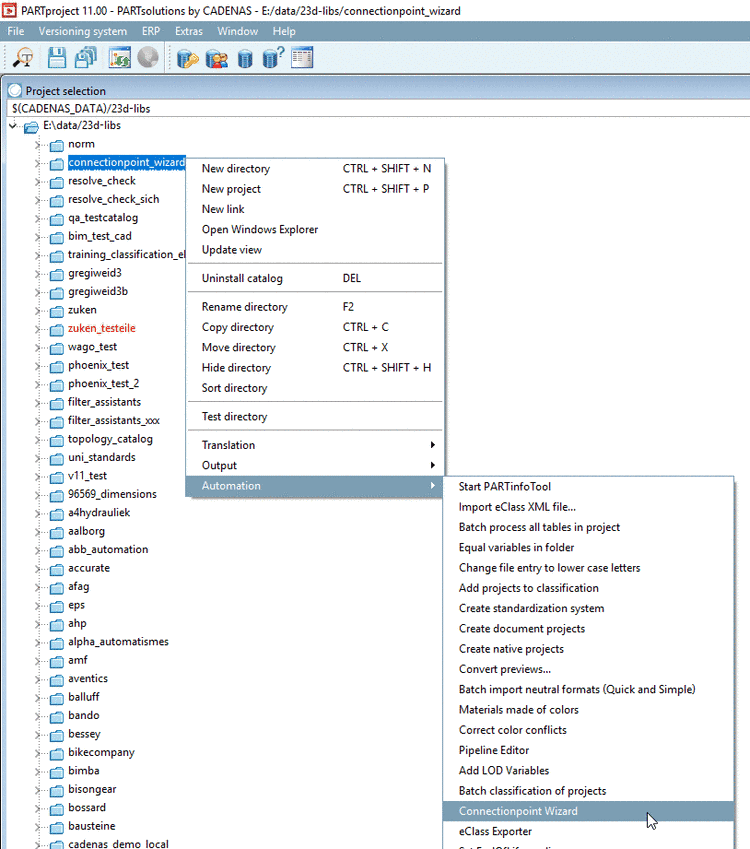
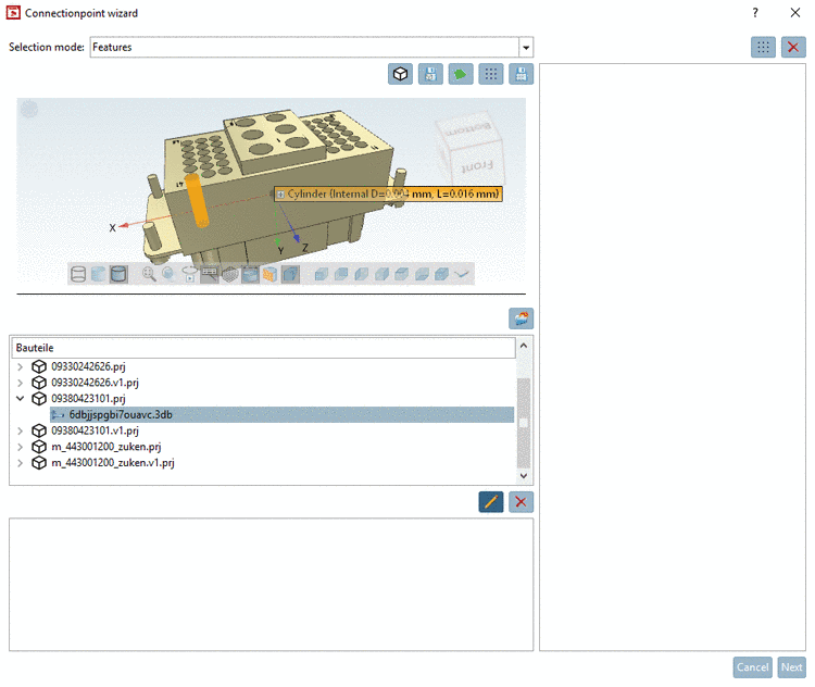
In the index tree, select the desired directory level. Then in the dialog area Parts, projects of the next lower level are displayed, which then can be edited.
-
In PARTproject, under Project selection -> context menu of catalog -> Automation call Connectionpoint Wizard.
-
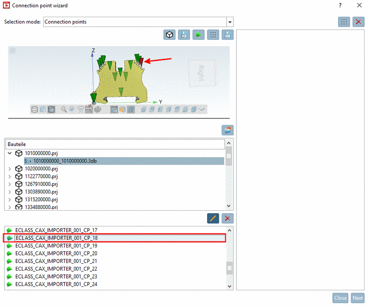
Select the 3db file of the desired part.
-
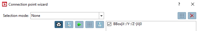
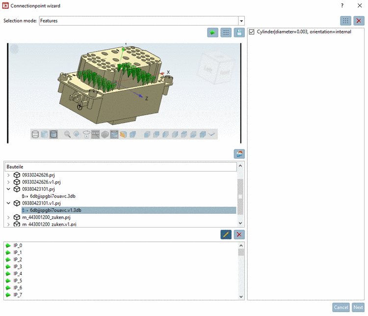
Under Selection mode, select one of the following options:
-
None: If no 3D selection is required. Choose this option when you want to place connection points on a corner of the BoundingBox. (The other options are also possible.)
See below.
-
Connection points: Choose this option if you want to detect the name of a connection point. When selecting a point in the 3D view, the point is marked in below listing.
-
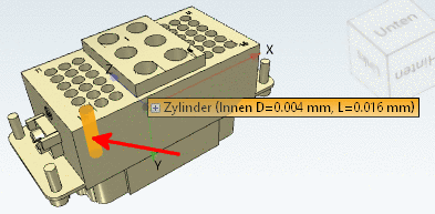
Features: Choose this option if you want to automatically set connection points on features, either single ones or for all identic features at once.
See below.
-
-
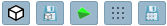
When selecting one of the functions
Create BoundingBox Cp (Ctrl+B) or Save BBox as template, under Selection mode,
no special option has to be selected.-
Create BoundingBox Cp (Ctrl+B)
With the help of this function you can create a connection point on a corner of the BoundingBox.
See below.
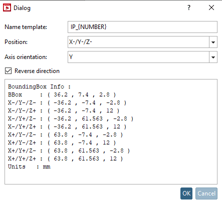
When clicking on the icon the respective dialog is opened.
Set the desired entry under Name template, Position, Axis orientation and Reverse direction and confirm with .
-> The connection point is placed on the desired corner of the BoundingBox.
-
When clicking on the button the same dialog box is opened like under Create BoundingBox Cp (Ctrl+B).
Make the desired settings and confirm with .
-> The template is saved and displayed in the dialog area on the right side.
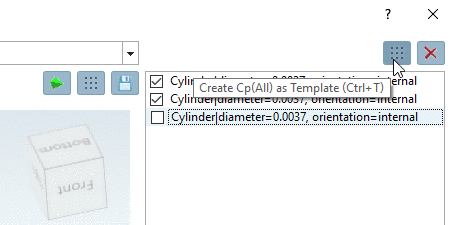
When clicking on
Create Cp(All) from Template (Ctrl+T) top right, you can set the respective
connection point on the BoundingBox directly from the activated
template.
When selecting one of the functions
Create Cp (Ctrl+C) (for a single feature), Create Cp (All) (Ctrl+A) (for all identic features) or Save as template (Ctrl+S), under Selection mode,
the option Features and in
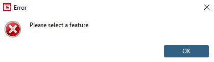
the 3D view, a feature has to be
selected.Otherwise an error message is displayed.
- Create Cp (Ctrl+C): A connection point is set on the selected
feature.
- Create Cp (All) (Ctrl+A): A connection point is set on the selected
feature and in addition for all identic features.
-
Save as template (Ctrl+S): With this function, you can create and save
templates. For this select a feature and then click on the
icon.
-> On the right side a template is displayed.
When clicking on
Create Cp(All) from Template (Ctrl+T) top right, you can create connection
points from the activated templates.
-

-
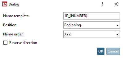
When clicking on one of the functions Create Cp (Ctrl+C), Create Cp (All) (Ctrl+A) or Save as template (Ctrl+S), a dialog box for the specification of the parameters Name template, Position, Name order and Reverse direction is opened.
In the following the procedure after selecting the function Create Cp (All) (Ctrl+A) is shown.
-
Name template: Accept the suggestion or adjust the expression as desired.
IP_{NUMBER} <default>IP_GROUP1_{NUMBER} -
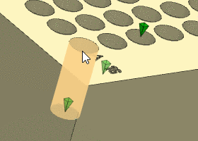
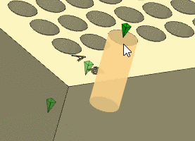
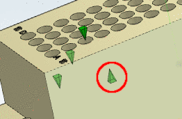
Position: Select the option Start, End or Center. The following figures illustrate the usage with the help of a cylinder.
-
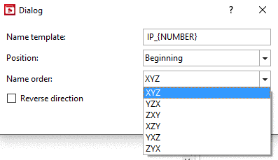
Name order: Determines the way of numeration, which is according to the priority of 3D coordinates.
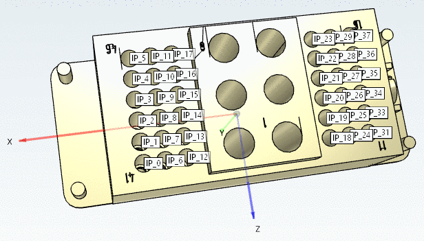
In the following exemplary figure the numeration is according to "XYZ".
Y doesn't matter, because all points have the same value for Y. The start point "IP_0" has the highest X and Y value. The second point has a X value of the same value, however, a lower Z value, etc. In the second row points with next higher X value follow, beginning with the highest Z value, etc.
-
Reverse direction: ... the orientation of the connection point is reversed
-
-
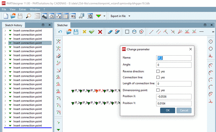
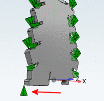
Following figure shows the state after application of the function Create Cp (All) (Ctrl+A)
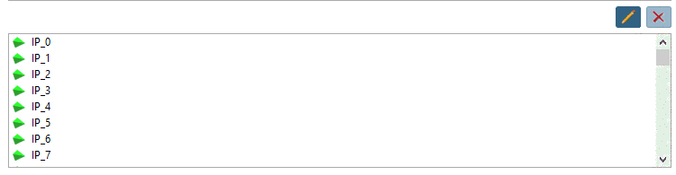
.In the dialog area on the very bottom, all created connection points are displayed.
After clicking
 , you can rename a connection point.
When clicking on
 , the selected connection point is deleted.


![[Tip]](/community/externals/manuals/%24%7Bb2b:MANUALPATH/images/tip.png)