Manual
Login
Our 3D CAD supplier models have been moved to 3Dfindit.com, the new visual search engine for 3D CAD, CAE & BIM models.
You can log in there with your existing account of this site.
The content remains free of charge.

Top Links
Manual
 |
For the placing of electrical engineering components in CAD the following shall apply:
The Connection point is in left below edge of bounding box of part (smallest possible enclosing cuboid with alignment along X,Y,Z axes).
-
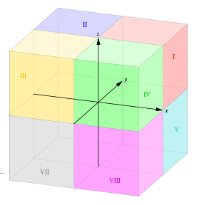
All axes of coordinate system are positive and Z axis point is oriented upwards (as in first octant).
Imagine the 3 dimensional space divided in 8 octants: The 1. octant (I) consists of points where all have three positive coordinates x,y,z.
In order to get a proper placement of part in most cases it will be necessary to shift the part along X, Y and Z axis.
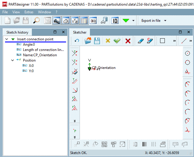
You can realize shift and rotation via dialog Fixed plane.
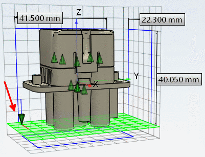
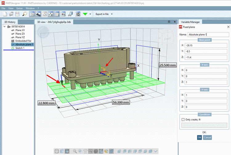
The following exemplary figure shows a part where the orientation is correct (Z upwards), so that only a shift has to be performed (see entries under Base point). As the Z axis shows upwards, no rotations of axes have to be performed. The input fields under X axis retain the default values 1,0,0. The input fields under Y axis retain the default values 0,1,0.

The connection point can be set with Angle 0, as no rotation is necessary or rotations are realized via plane.
The coordinates of connection point under "Position" can be left at 0,0, so that the connection point is in the Base point of plane.
![[Note]](/community/externals/manuals/%24%7Bb2b:MANUALPATH/images/note.png) |
Note |
|---|---|
Alternatively, a needed shift can also be performed here in the sketch instead via dialog Fixed plane -> Base point. | |
For parts with wrong orientation you have to perform respective adjustments in the dialog Fixed plane under X axis and Y axis.
After transformation (rotation + shift) applies:
Example with rotation: The transformation happens with 2 rotations.
The original X axis is mapped to the Z axis (Z=1) and then the original Y axis to the X axis (X=1).

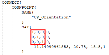
In an exported PS3 file you can check orientation and shift of connection point:
-
Example 1 (no rotation of axes):
x axis is mapped to x axis, y axis is mapped to y axis, z axis is mapped to z axis.
The lowest line shows the shift in direction of x, y and z axis.
-
Example 2 (with rotation of axes):
x axis is mapped to the negative z axis, y axis is mapped to the y axis, z axis is mapped to the x axis.
The lowest line shows the shift in direction of x, y and z axis.