Manual
Login
Our 3D CAD supplier models have been moved to 3Dfindit.com, the new visual search engine for 3D CAD, CAE & BIM models.
You can log in there with your existing account of this site.
The content remains free of charge.

Top Links
Manual
 |
After you have clicked on Transfer to CAD
 (in PARTdataManager),
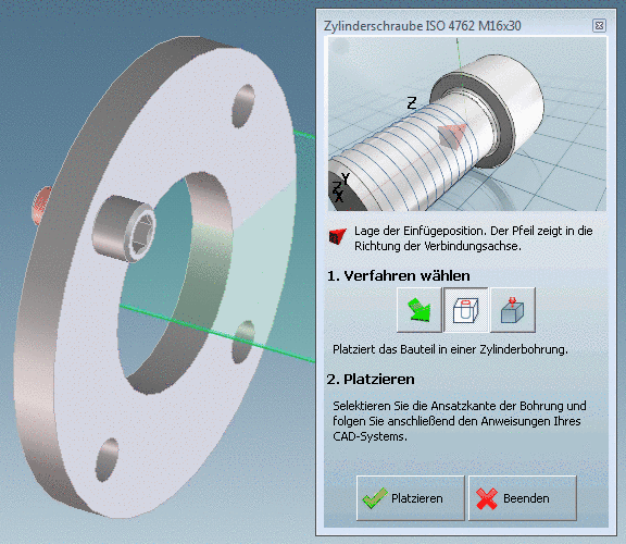
the view returns to CoCreate Modeling and the PARTsolutions placement
dialog opens.
(in PARTdataManager),
the view returns to CoCreate Modeling and the PARTsolutions placement
dialog opens.-
Select the desired placement method under 1. Select method via one of the following buttons:
If the checkbox Repeating is activated, then the placement is automatically repeated as long as the user clicks on . The next placement is started after the user has confirmed the placement in the CAD.
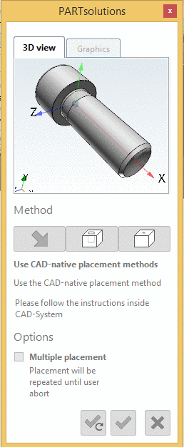
-> After you have chosen a placement method, the CoCreate Modeling placement dialog opens.
-
If there are several insertion positions possible, the dialog is adjusted and the message "2. Select insert position" appears.
Select the desired insertion position from the list.
-> The CoCreate Modeling placement dialog opens.
For the first placement it is not necessary to click on .
When the first placement is finished, the part can be inserted via again. If the checkbox Repeating is activated, then the placement procedure is automatically repeated as long as the user clicks on . The next placement is started after the user has confirmed the placement in the CAD.
By clicking on the PARTsolutions placement dialog is closed.
-
-
As long as the user has to interact in the CAD, the PARTsolutions placement dialog is deactivated in order to enable a clear user guidance.
If you cancel or finish the placement procedure the dialog is activated again.
After starting the CoCreate Modeling placement procedure: If the desired part is not available in the opened model yet, it is tried to load the part from ModelManager - if active - or from the pool - if set. This may last a moment.

![[Note]](/community/externals/manuals/%24%7Bb2b:MANUALPATH/images/note.png)
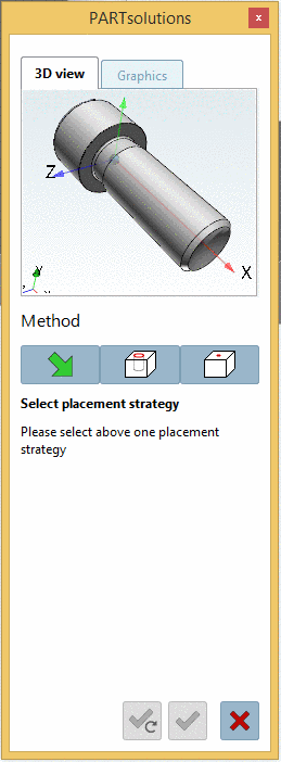
In the following the procedure of the individual placement methods is explained:
-
-
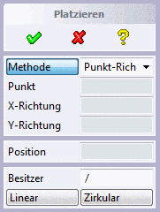
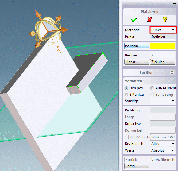
There are two different placement methods available, which you can select via list field:
-
-
You have exported a PARTsolutions part into the CAD and now want to place it with the Point-Direction method.
-
Now determine the X direction.
-
-> The part is placed at the desired position.
Click on the and select the desired axis.
-
-> Now the part is defined in X and Y direction.
By clicking on you can still place the part with the CAD methods optionally.
-
-
Determine the insertion point as described above.
By clicking on you can still place the part with the CAD methods optionally.
-
User: Via User you can choose an alternative assembly, where the part shall be inserted. This step is performed not until you confirmed via
 or pressed the button or .
-
| : Via or the placement is successfully finished and the creation of a pattern is started.
These dialog fields are a CoCreate internal function.
-
-
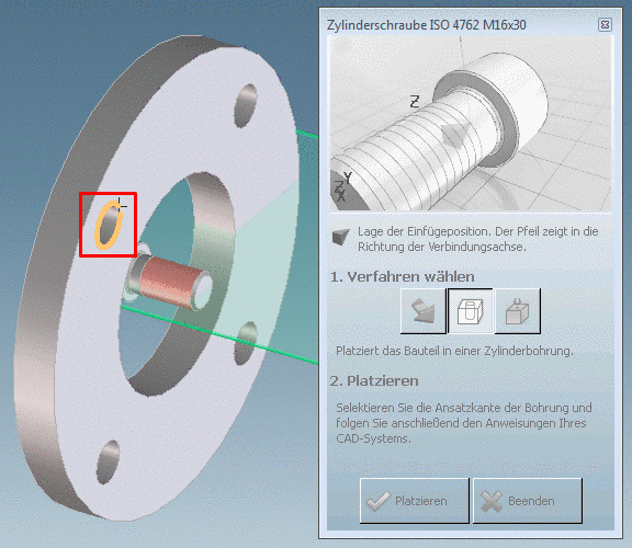
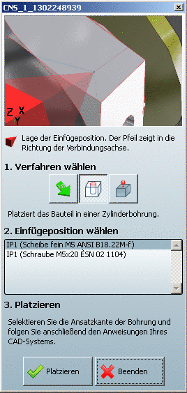
PARTsolutions placement dialog In Cylinder

At this place there are two variants:
-
The part to insert has several possible insertion points.
In this case the enhanced dialog is displayed.
Select the desired Insertion position from the list.
-> The PARTsolutions placement dialog is deactivated.
The further procedure is identically with the described in the following point.
-
The part to insert has only one insertion point.
-
The PARTsolutions placement dialog is deactivated.
-> First the exported part is inserted in the assembly without placement.
-
In CoCreate the respective dialog is opened.
-
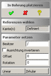
-> Under "Reference" the entry "Defined" appears.
-> The part is placed at the insertion point. (You can cancel via
 anytime.)
 Via User (Besitzer) you can choose an alternative assembly, where the part shall be inserted. This step is performed not until you confirmed via
or pressed the button or
.You can invert the orientation of the part via Invert orientation (Ausrichtung invertieren) (rotation with 180° around the X axis of the part). The view is refreshed.
You can offset the part orthogonally to the plane by selecting circle edges. The value for all edges is identically. The view is refreshed after input.
You can rotate the part around the circle axis. The value for all edges is identically. The view is refreshed after input.
-
Via the buttons or the placement is successfully finished and the creation of a pattern is started.
The dialog fields are a CoCreate internal function.
The buttons and are only available at selection of a single edge.
-
After the first placement with one of the methods the button changes to the button . You can place a part any number of times.
-
-
-
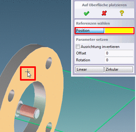
PARTsolutions placement dialog On surface
 .
.At this place there are two variants possible:
-
The part to insert has several insertion points:
In this case the enhanced dialog is displayed.
Select the desired Insertion position from the list.
-> The PARTsolutions placement dialog is deactivated.
The further procedure is identically with the one described in the following point.
-
The part to insert has only one insertion point.
-
The PARTsolutions placement dialog is deactivated.
-> First the exported part is inserted in the assembly without placement.
-
In CoCreate Modeling the respective dialog is opened.
On the desired plane click on the desired insertion point.
-> Under Position the entry "Defined" appears.
-> The part is placed at the insertion point. (You can cancel via
anytime.)In the CoCreate dialog there are further setting options in addition:
-
Via User (Besitzer) you can choose an alternative assembly, where the part shall be inserted.
This step is performed not until you confirmed via
or pressed the button or
. You can invert the orientation of the part via Invert orientation (Ausrichtung invertieren) (rotation with 180° around the X axis of the part). The view is refreshed.
You can offset the part orthogonally to the plane by selecting circle edges. The value for all edges is identically. The view is refreshed after input.
You can rotate the part around the circle axis. The value for all edges is identically. The view is refreshed after input.
Via the buttons or the placement is successfully finished and the creation of a pattern is started.
-
After the first placement with one of the methods the button changes to the button . You can place a part any number of times.
-
-
-
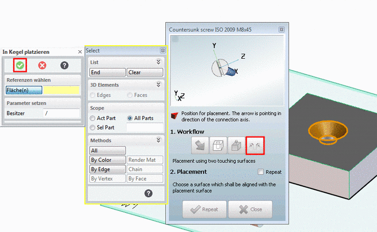
PARTsolutions placement dialog Touching Surfaces
 .
.At components classified respectively the button Touching Surfaces is displayed.
-> The respective dialog opens.