Manual
Login
Our 3D CAD supplier models have been moved to 3Dfindit.com, the new visual search engine for 3D CAD, CAE & BIM models.
You can log in there with your existing account of this site.
The content remains free of charge.

Top Links
Manual
 |
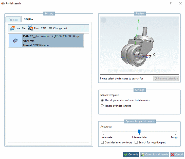
You can use any 3D file as search part:


-
In the History section, select the 3D files tab.
-
A number of formats can be opened:[58]
-
![[Note]](/community/externals/manuals/%24%7Bb2b:MANUALPATH/images/note.png)
Note When using the STEP format topology information/features are loaded in best quality (if the license "PSADDONS*ADVANCEDTOPO" is available).
Then Sphere, Torus and Elongated Cylinder are available in addition. All other features are read in with much higher quality.
Also see Section 3.1.6.4.9.7, “Quality of topology information/features”.
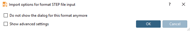
When selecting the STEP format the dialog box Import options for format STEP file input is opened.
-
If there is an ambiguity for a file extension, an additional dialog box appears.
Ambiguities are possible for a file extension such as
.prtfor example, which is used by Creo Elements and NX as well, furthermore for several versions of a CAD system.In the list field select the desired system and the desired version.
-
Then the dialog box Selection of unit is opened.
In the list field, select the correct unit: mm, cm, dm , m, INCH, FEET, INCH/10, INCH/100
-> The file is loaded in the dialog box on the left side. On the right side the part is shown in the 3D preview.