Manual
Login
Our 3D CAD supplier models have been moved to 3Dfindit.com, the new visual search engine for 3D CAD, CAE & BIM models.
You can log in there with your existing account of this site.
The content remains free of charge.

Top Links
Manual
 |
|
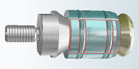
The characteristic chosen in the Table or List is immediately displayed in the 3D window. For visual component testing there are a number of functions available to you: |
|
-
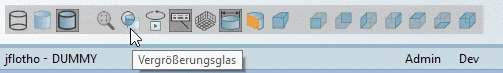
To control the 3D preview use the buttons of the 3D preview toolbar.The most important functions are summarized here.
If you move the cursor over the buttons, the display of a button changes from dimmed to full-color.
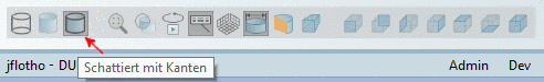
Activated buttons (Shaded with edges exemplarily in the next figure) are displayed a little bit darker.
More detailed information about the individual buttons can be found under Section 3.1.7.6.1, “ 3D view Toolbar ”.
-
With the mouse functions left mouse button, right mouse button, both right and left mouse button pressed at the same time you can carry out the following operations:
-
By right-clicking into the 3D window you reach the context menu.
There you have some commands of the 3D toolbar available in parallel, in addition some more commands:
Define sectional plane... (see Section 3.1.7.6.7, “ Define section cut... ”)
Measure... (see Section 3.1.7.6.3, “ Measurement of 3D parts ”)
Measure grid (see Section 3.1.7.6.4, “ Measuring grid ”)
A detailed description of all context menu commands can be found under Section 3.1.19.3.2.3, “Context menus: 3D / 2D / Technical specifications”.
More detailed information about the individual buttons of the toolbar can be found under Section 3.1.7.6.1, “ 3D view Toolbar ”.
-
The coordinate system is displayed on the bottom left per default. You can change this under Extras -> Settings.... (on/off, position).
-
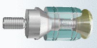
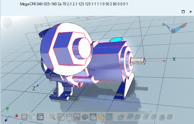
With a pair red-cyan glasses you can see the assembly even more realistically in 3D.
The default display is on the top right. You can change the display under Extras -> Settings.... (on/off, position).