Manual
Login
Our 3D CAD supplier models have been moved to 3Dfindit.com, the new visual search engine for 3D CAD, CAE & BIM models.
You can log in there with your existing account of this site.
The content remains free of charge.

Top Links
Manual
 |
In the following is described how to export a connection from PARTsolutions, place it in CoCreate Modeling and optionally set a hole in the element to bolt.
-
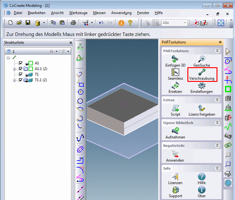
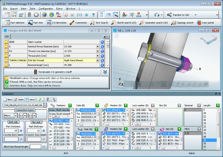
In the PARTsolutions menu call up the menu item Connection.
-
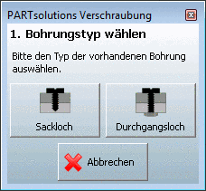
Determine whether a blind hole or a through hole shall be created.
-> The PARTsolutions connection dialog changes, but is still active.
-> Furthermore the CoCreate Modeling dialog "Durchgangsloch" ("Through hole") appears.
-
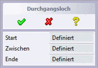
Now determine the thickness of the bolting elements by clicking adequate elements (e.g. plane, edge).
-> Afterwards in the CoCreate Modeling dialog "Durchgangsloch" ("Through hole") in all three fields "Definiert" ("Defined") is displayed.
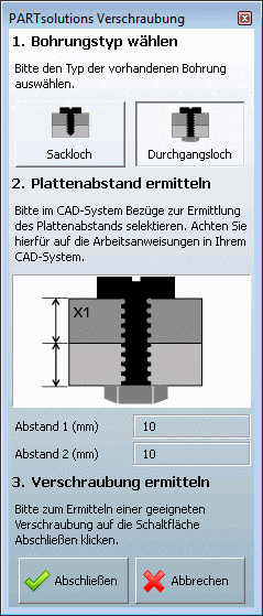
Furthermore the PARTsolutions connection dialog is active now.
The calculated thickness is displayed.
-
In PARTdataManager determine the connection components.
Detailed information on connections is found under Section 3.1.1.10, “ Connections ”.
-
Optionally you can export holes in addition.
In this case you also determine the hole type in the columns Hole (B) / Hole (N).
In the Connection menu
 , on the icon Export holes on/off you have to set
"On".
, on the icon Export holes on/off you have to set
"On". -
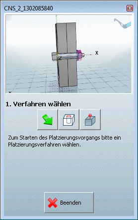
Click on the button Transfer to CAD.
-> The view returns to CoCreate Modeling with opened dialog 1. Select method.
-
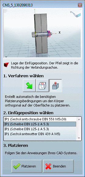
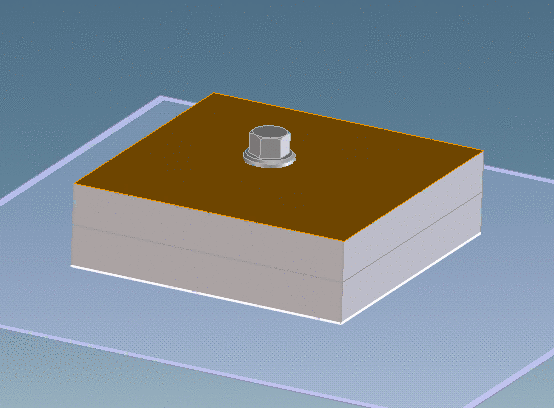
Select the correct Insertion point.
-
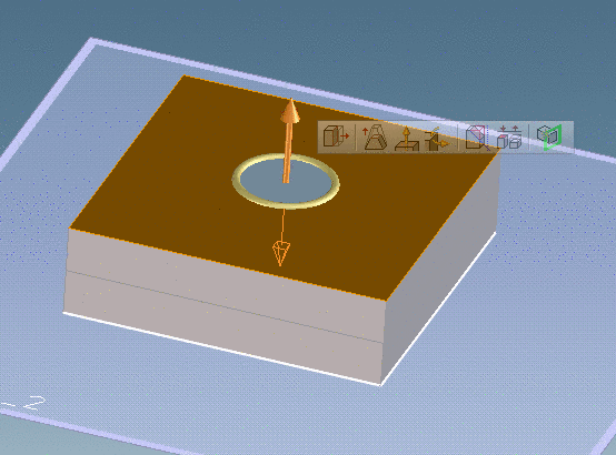
On the bolting element click on the desired insertion position.
-
In the PARTsolutions dialog click on .
-
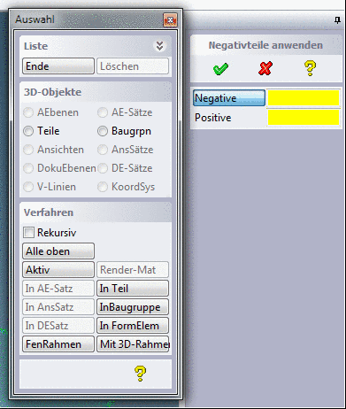
Optionally set the hole: (The exact behavior can slightly differ between the different versions.)
In the PARTsolutions menu under Negativteile (Negative parts) click on Apply.
-> The dialog "Auswahl" ("Selection") opens.
- In the dialog "Negative" select the desired PARTsolutions connection elements.
- In the dialog "Positive" select the desired target parts, which shall be cut.
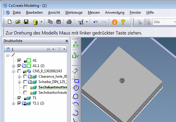
-
In order to check the hole hide the connection elements.