Manual
Login
Our 3D CAD supplier models have been moved to 3Dfindit.com, the new visual search engine for 3D CAD, CAE & BIM models.
You can log in there with your existing account of this site.
The content remains free of charge.

Top Links
Manual
 |
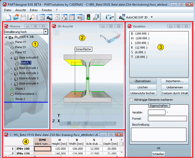
In the top part of the PARTdesigner interface you will see the title bar , with the file name and respective path of the opened part.
Below this, you will find the menu bar, with which a row of menus can be activated.
And below this then is the toolbar, in which commands for icons can be launched.
The actual interface is divided into the following areas:
-
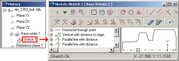
The History area is, aside from the Sketcher the central "showplace" within the PARTdesigner. Via its context menus, the Sketcher is opened (see Fig. „Interface with Sketcher“) and the part is created. In addition, the history documents many construction steps , so that each part assembly can later be retraced and possibly even modified.
-
In PARTdesigner variables - instead of dimensioning values - are arranged, for which there are concrete values already set in the tables.[34]This method has the advantage that a new sketch must not be made for each part value.
In the Variables menu area, you can apply new variables as well as change details to existing variables.
-
The table shows up in the lower part of PARTdesigner. Per mouse-click in the respective table entry, the respective part automatically displayed in the 3D view.
-
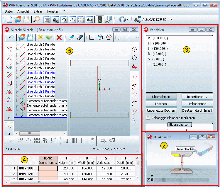
A 3-D solid must basically be created via a 2-D sketch. This 2-D sketch is created in the Sketcher dialog area.
Here, through individual constructions steps, the sketches are created which later then create the basis for extrusions and rotations in the History dialog area.
![[Note]](/community/externals/manuals/%24%7Bb2b:MANUALPATH/images/note.png)
The two following images show the interface once with and once without Sketcher.