Manual
Login
Our 3D CAD supplier models have been moved to 3Dfindit.com, the new visual search engine for 3D CAD, CAE & BIM models.
You can log in there with your existing account of this site.
The content remains free of charge.

Top Links
Manual
 |
-
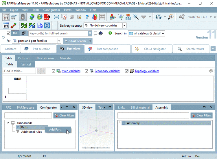
In the docking window Configurator, via secondary mouse key, call the context menu of Parts.
-
Click Insert part.... -> The window Open file appears and the Project Files (*.prj) are displayed.
-
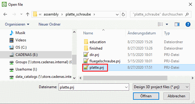
Under .../partsolutions/23d-libs/training/assembly/platte_schraube, pick the part you want to insert as Start element (here plate.prj).
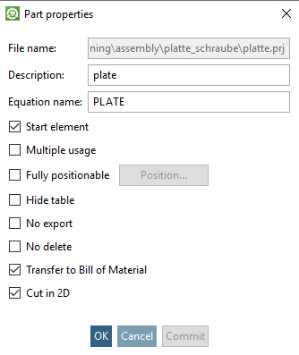
-> The dialog box Part properties is opened.
![[Note]](/community/externals/manuals/%24%7Bb2b:MANUALPATH/images/note.png)
Note If an Assembly Table Project shall be created from a configuration, you have to use a dummy starter-part. On this see Section 9.8, “Example 2 - Create an Assembly Table Project ”.
-
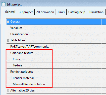
Specification of part color: In older versions, at this place, the part color could be specified. As of version 11, please set color information under Edit project -> tabbed page General -> Color and texture or preferably under Render attributes.
-
-
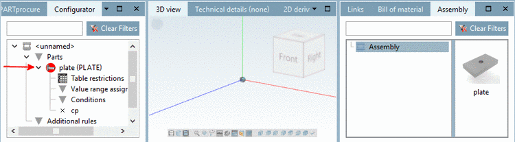
After you have confirmed with in the Part properties dialog area, the first part (plate) is displayed in the Configurator as subordinated directory.
The part symbol is highlighted in red and thus identified as start element.
-> Below the part name you can find the directories Table restrictions, Value range assignments and Conditions (see Section 9.5.1.4, “Context menu of "Table restrictions" directory ” ff.).
-> The x icon (besides the name of connection point) stands for the Connection point, which was assigned to the part in PARTdesigner.
-> In the dialog area Assembly, the plate is inserted as preview.