Manual
Login
Our 3D CAD supplier models have been moved to 3Dfindit.com, the new visual search engine for 3D CAD, CAE & BIM models.
You can log in there with your existing account of this site.
The content remains free of charge.

Top Links
Manual
 |
-
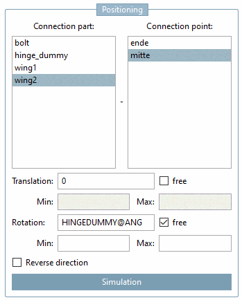
Connection part and Connection point:
Assign connection parts to the currently selected connection point. The selection of part and its connection point is performed via these two fields. In above figure the connection point is "part2" with connection point "IP1KNUEBELOK".
-
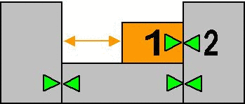
Translation: Distance between two connection points (via value or variables). In the figure below the profile shifts (later on in the CAD-system) in the defined distance between the connection points 1 and 2.
In the input field of Translation, the start position of the movable element in CAD is defined.
-
The option free allows assembly components transferred from PARTdataManager into a CAD system, to be freely rotated around the translation axis.
If the option Free is activated, a minimum and maximum position can be specified (see next point).
-
Min and Max specification is used in order to effect the restriction also in CAD system.
-
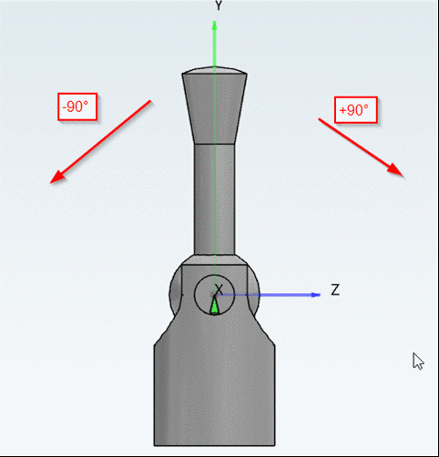
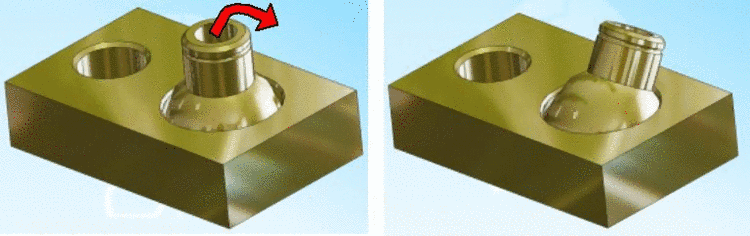
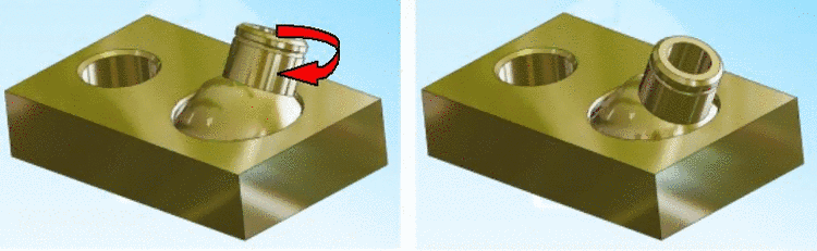
Rotation: The part rotates around a connection point (via angle or variables).
In the input field of Rotation, the start position of the movable element in CAD is defined.
-
The option free allows assembly components transferred from PARTdataManager into a CAD system, to be freely rotated around the rotation axis.
If the option Free is activated, a minimum and maximum position can be specified (see next point).
-
Min and Max specification is used in order to effect the restriction also in CAD system. For example, a lever could only be moved in the set range.
![[Note]](/community/externals/manuals/%24%7Bb2b:MANUALPATH/images/note.png)
Note Please also have a look on the example on this.
-
Reverse direction: The part is rotated 180 degrees at the connection point concerning the Z axis.
-
Details on this can be found under Section 3.6, “Simulation”.
-
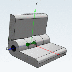
Tilt: ...allows inclination related to a connection point.
-
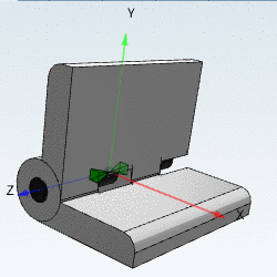
Swivel: ...enables turning in an inclined position.