Manual
Login
Our 3D CAD supplier models have been moved to 3Dfindit.com, the new visual search engine for 3D CAD, CAE & BIM models.
You can log in there with your existing account of this site.
The content remains free of charge.

Top Links
Manual
 |
In assemblies, the selection of certain characteristics does not happen via tables of single parts, but via a superordinated table, which is in the so-called dummy starter part.
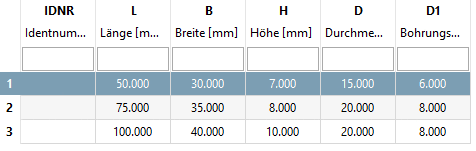
As a basis for this superordinated table (the later assembly table) use the table of a significant single part. Here in this example this is the table of a wing. The variables of the bolt will be brought into dependency to the variables of the wing, so that they don't have to be part of the assembly table explicitly.
The table also contains variables only used by the assembly, which do control functional characteristics like angularity or rod position, for example. Here in this example this is the angularity of the hinge. And this table is the actual assembly table.
The dummy starter part is a 3D project (single part) WITHOUT GEOMETRY (without features), it serves as "Starter part", and contains ONE! Connection point for the actual assembly and is not not exported.
-
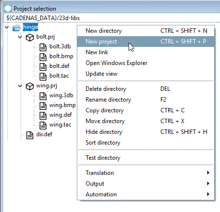
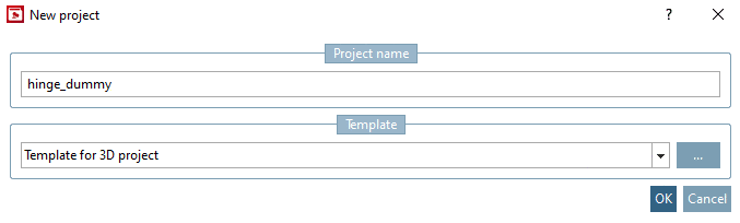
Create a dummy starter part as new project "hinge_dummy" with Template for 3D project.
-
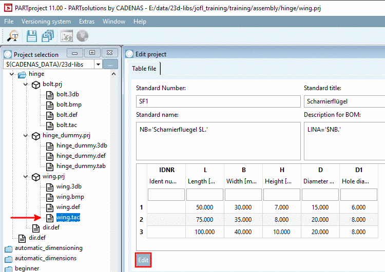
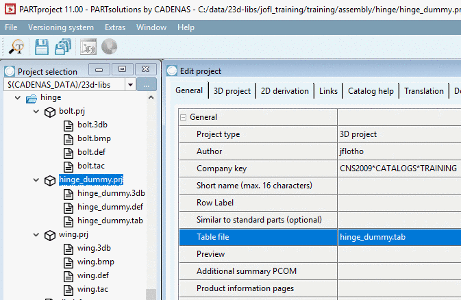
Mark the file "wing.tac" in "wing.prj" and under Edit project -> Table file, click on .
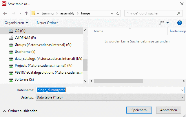
-> PARTdesigner is opened. Save the file as "hinge_dummy.tab or .tac". (Confirm with "Yes" - if the query "Replace?" pops up.)
In PARTproject, make sure that the file "hinge_dummy.tab" is selected in the list field under Edit project -> General -> General -> Table file.
-
In PARTproject, mark the file "hinge_dummy.tab" and in the docking window Edit project, click on .
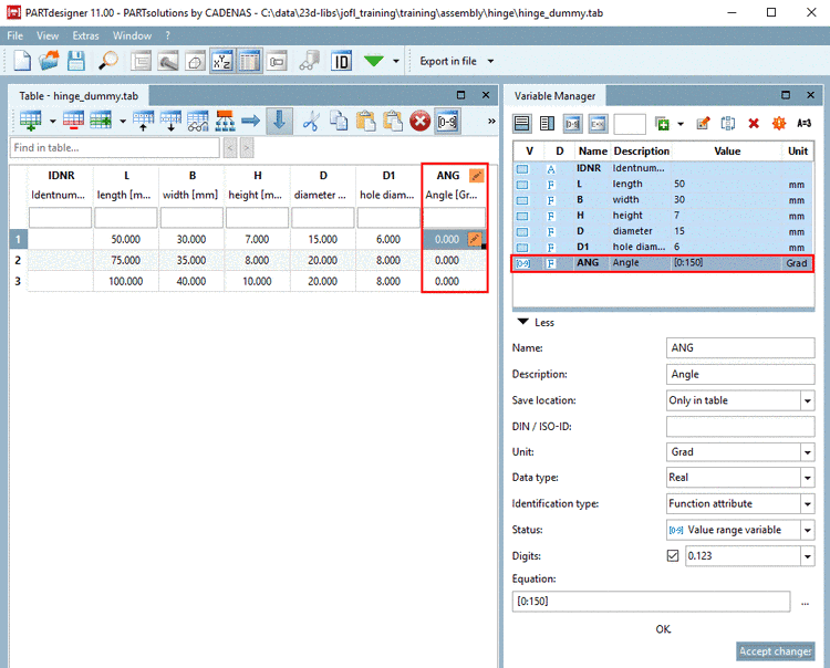
Add a variable ANG to control the angularity of the hinge.
Here in this example following settings are made:
Save location: Currently just Only in table is available. At the latest when setting the connection point, In geometry and table has to be set.
Status: Select Value range variable. Under "ANG", the opening angle of the hinge can be inserted.
-
Equation: Choose an opening angle of the hinge (e.g. 0 to 150 degrees).
[0:150]
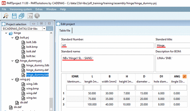
NB='Hinge $L.$ANG.'
-
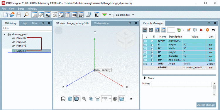
Open "hinge_dummy.3db" and add the Connection point for the actual assemblies.
In geometry and tableAccept the changes and save the file.
![[Note]](/community/externals/manuals/%24%7Bb2b:MANUALPATH/images/note.png)