powered by CADENAS

Manual

Manual

3.1.9.2.3. "Layers" and "Export options" tabbed page - AutoCAD DWG 2D

[Note] Note
  • When exporting into the dwg file, the information of the tabbed page Layers is stored in the file.

    Example: "Thick lines" are mapped to layer "AM_0" and are stored in the dwg file in yellow.

    Example: "Thick lines" are mapped to layer "AM_0" and are stored in the dwg file in yellow.

    If the file is imported into an existing drawing, then AutoCAD settings have priority.

    Example: Mechanical-Layer-Manager: AM_0 = white. The inserted part is depicted with white "Thick lines".

    Example: Mechanical-Layer-Manager: AM_0 = white. The inserted part is depicted with white "Thick lines".

    If the file is opened apart, then the depiction will be with the layer color specified in the dwg file.

  • Layers not existing in AutoCAD are created according to the defaults.

  • If you want to override AutoCAD layer information, then use the tabbed page Export options.

    Example: In this case the "Thick lines" are depicted in blue.

    Example: In this case the "Thick lines" are depicted in blue.

  • Tabbed page Layers

    Tabbed page "Layers" - AutoCAD DWG 2D

    Tabbed page "Layers" - AutoCAD DWG 2D

    • Open directory after export(once)

    • Destination file

    • Version

  • Tabbed page Export options

    Tabbed page "Export options" - AutoCAD DWG 2D

    Tabbed page "Export options" - AutoCAD DWG 2D

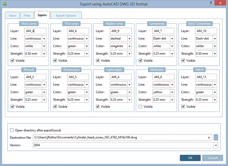
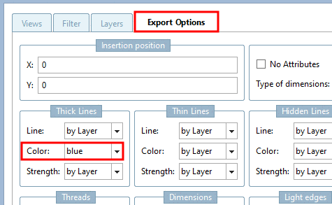
    • Insertion position: The insertion position in the CAD system can already be set in PARTsolutions - assuming your CAD system supports this function. Enter the X and Y coordinates.

    • Options:

      • Insert into AutoCAD after document creation:

      • No Attributes: ...prevents certain attributes (for example texts from PARTproject) from being transferred to the CAD system during export

      • Type of dimensionings:

        • Automatic:

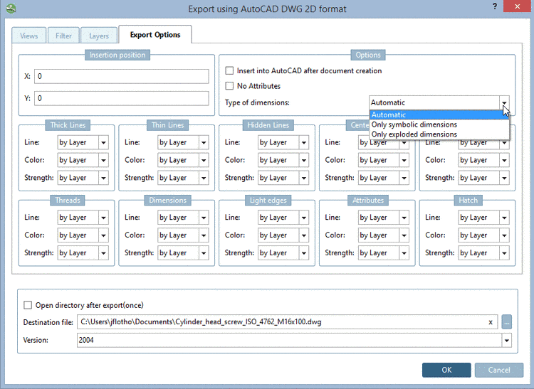
          If a symbolic dimensioning can be created then it is used, otherwise the exploded.

        • Only symbolic dimensions:

          A dimensioning created in eCAT or created in PARTdataManager before the export is detected as such.

          When using this option the dimensioning is created as "real" dimensioning. After selection the respective dialog is displayed.

        • Only exploded dimensionings:

          Dimensioning and text are only displayed as exploded elements.

    • Line and color settings:

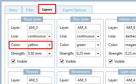
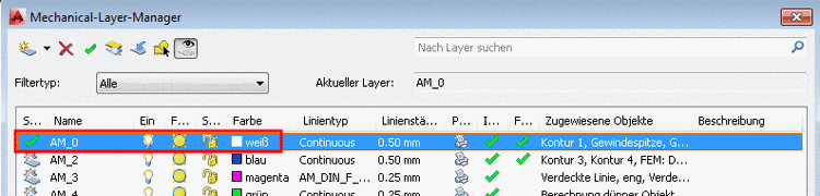
      Per default, the settings are set to by layer. Color and line settings depend a) on the layer settings in the CAD system or b) on the settings on the tabbed page Layers. In the list fields, you can explicitly select other settings for lines and colors, which then override the layer settings.