Manual
Login
Our 3D CAD supplier models have been moved to 3Dfindit.com, the new visual search engine for 3D CAD, CAE & BIM models.
You can log in there with your existing account of this site.
The content remains free of charge.

Top Links
Manual
 |
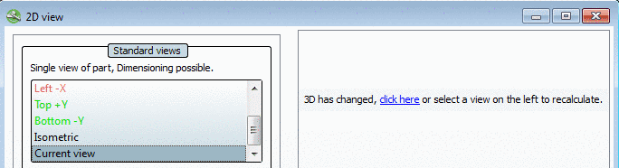
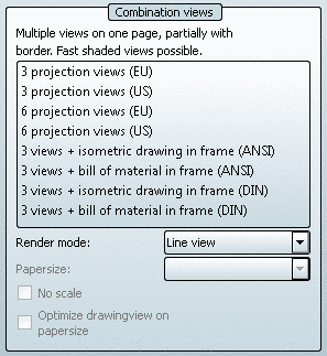
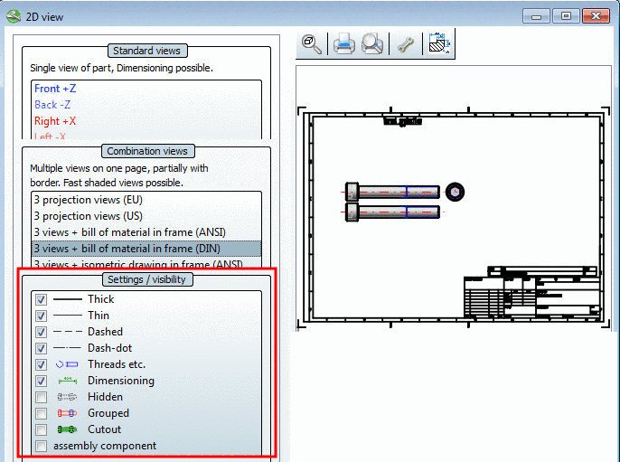
- 3.1.1.11.3.1.1. Standard views
- 3.1.1.11.3.1.2. Combination views
- 3.1.1.11.3.1.3. Settings / visibility
- 3.1.1.11.3.1.4. Alternative 2D size Optimize drawing view on paper size /
- 3.1.1.11.3.1.5. Add dimensioning in PARTdataManager before the export
- 3.1.1.11.3.1.6. Transfer special derivations or technical views to CAD system
Selection and settings within the 2D view window, create the basis for the display of the object in your CAD system.
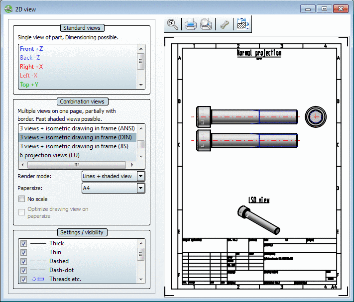
As soon as you click on a view, the 2D derivation of the part is created.
![[Note]](/community/externals/manuals/%24%7Bb2b:MANUALPATH/images/note.png) |
Note |
|---|---|
An exception for Combination views is the option Shaded view. Here the 2D derivation is only created in case of an export to the CAD system. See more under Section 3.1.1.11.3.1.2, “ Combination views ”. | |
-> Once all
settings have been made, click on  Transfer to CAD.
The settings area of the dialog page is subdivided as follows:
The individual areas are explained in the following sections.
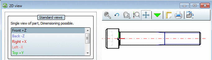
The following individual views are available:
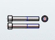
The Derivation view "Line view" is used automatically for the individual views.
Manual dimensioning is possible. See Section 3.1.1.11.3.1.5, “Add dimensioning in PARTdataManager before the export ”.
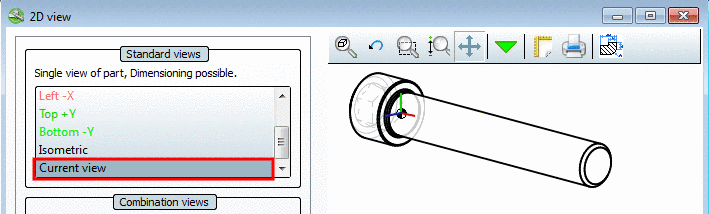
Optionally you can derive the current 3D view. See Section 3.1.1.11.3.1.1.1, “ Current view ”.
|
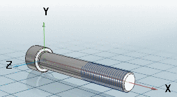
If you want to import the currently set direction of the coordinate system from the 3D view into the 2D derivation, in the list field select the option Current view. |
|

|
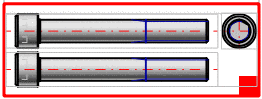
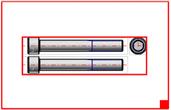
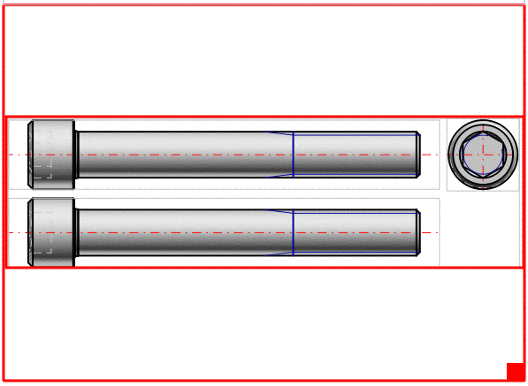
With frame:[a] |
|
|
|
|
[a] The views with frames may be modified. Even the creation of completely new views is possible, See Section 5.4.4, “ 2D derivation: create own views ” in eCATALOGsolutions Manual. | |
Render mode: See Section 3.1.1.11.3.1.2.1, “ Render mode ”.
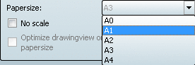
Paper size: See Section 3.1.1.11.3.1.2.2, “ Scale and Paper formats ”.
No scale: See Section 3.1.1.11.3.1.2.2, “ Scale and Paper formats ”.
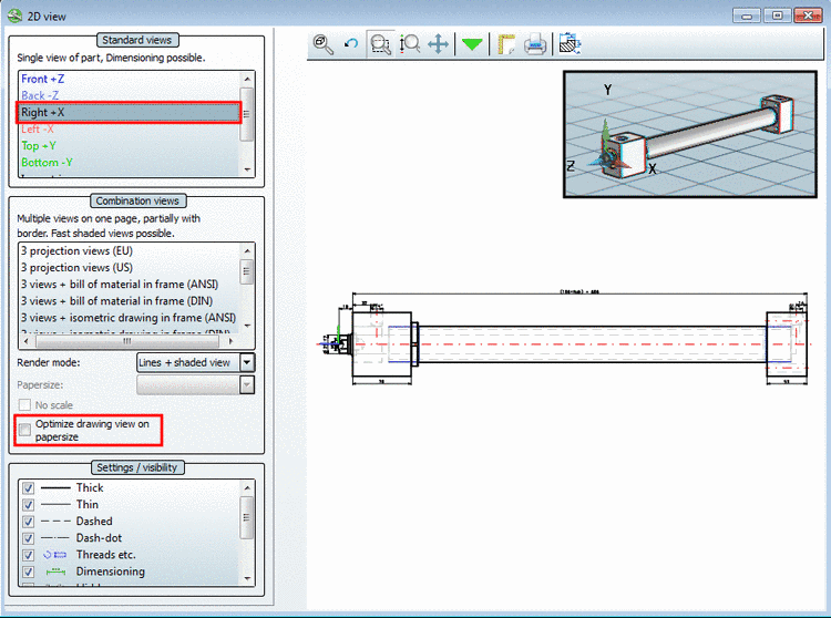
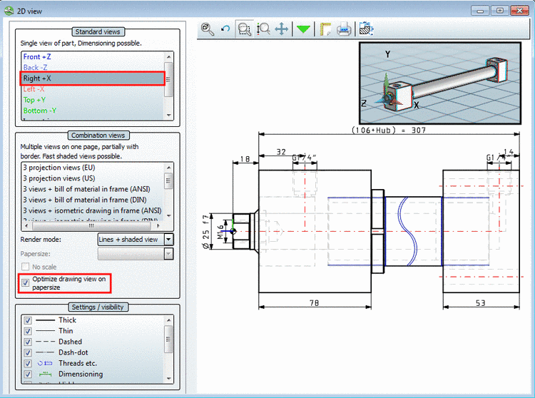
Optimize drawing view on paper size: This option is only then active, when a shortened view has been created for the part in addition. On this see under Section 3.1.1.11.3.1.4, “ Alternative 2D size Optimize drawing view on paper size / ”.
In the list field under Render mode the display under the derivation may be changed:
Choose one of the following options in the list field:
-
-
-
Here a gridded image is displayed, into a 2-D derivation. The derivation is only created if an export to the CAD system follows.
Note This render mode is also used for creating 3-D datasheets [75] See under Section 3.1.2.1.2.5.3, “Export PDF datasheet ”. The speed factor comes into play here.
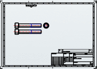
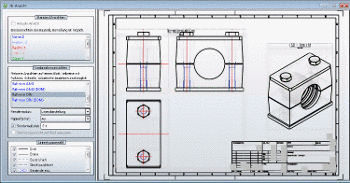
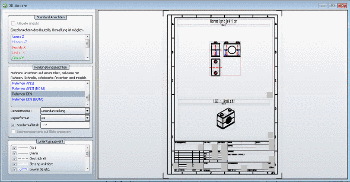
For the following views, the display can be exported with a sketch frame or with a sketch frame and integrated BOM-list.
|
Note |
|---|---|
Depending on type the respective paper formats are displayed. On this see under Section 3.1.1.11.3.1.2.2.2, “Adjust paper format in 2D view”. | |
The following adjustments may be made:
See the following sections for more information.

-
Option No scale deactivated (scale used):
Within the given frame the most fitting scale is used. The scale is displayed in the title (possibly only visible after enlargement).[76]
-
Within the given frame the entire available space is used. (Usually the derivations then increase in size.)

In the list field under Paper formats select the desired format. (Either A0 to A4 for DIN or A to E for ANSI)[77]
-> Scaling is adjusted automatically. As described under Section 3.1.1.11.3.1.2.2.1, “ Scale, position sketch elements in 2D view”, you may change it.
-
In the Grouped mode, the respective part can at first only be opened collectively after export to your CAD system. In order to be able to address individual lines in parts or individual components in assemblies, you must dissolve the group again.
-
assembly component refers to the preferred hatching direction in assemblies. If activated, then the assembly is treated as component and all parts of the assembly are hatched in the same direction in a cut.
The difference is especially eye-catching with bearings.
Normally outer and inner rings are hatched reverse. If the assembly component option is activated, then they are hatched in the same direction.[78]
-
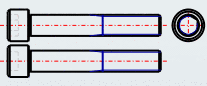
Optimize drawing view on paper size is a special feature for catalogs with parts which look bad in the 2D derivation due to their proportions.
This may happen with long cylinders, for example. The 2D derivation would then appear to be more of a line than a cylinder.
-
If the part contains an additional shortened view, the user can select between the standard display and the shortened view by checking the box Optimize drawing view on paper size in the 2D view dialog. Otherwise the checkbox remains inactive.
Before you export a 2D derivation into the CAD system, you can add a dimensioning.
-
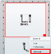
Click the Dimensioning mode command in the context menu of the view.
Note A detailed description of the functions in dimensioning mode you can find under Section 3.1.1.11.3.1.5, “Add dimensioning in PARTdataManager before the export ”.
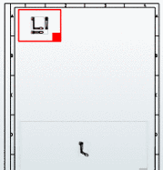
-
The part is transferred to CAD with dimensioning.


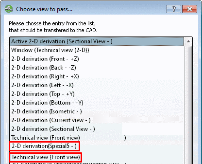
If customer sided provided you can transfer additional derivations to the CAD system in the Choose view to pass... dialog box (exemplified below "Special5").
Furthermore the technical views are displayed in the dialog box and can also be transferred to the CAD system.
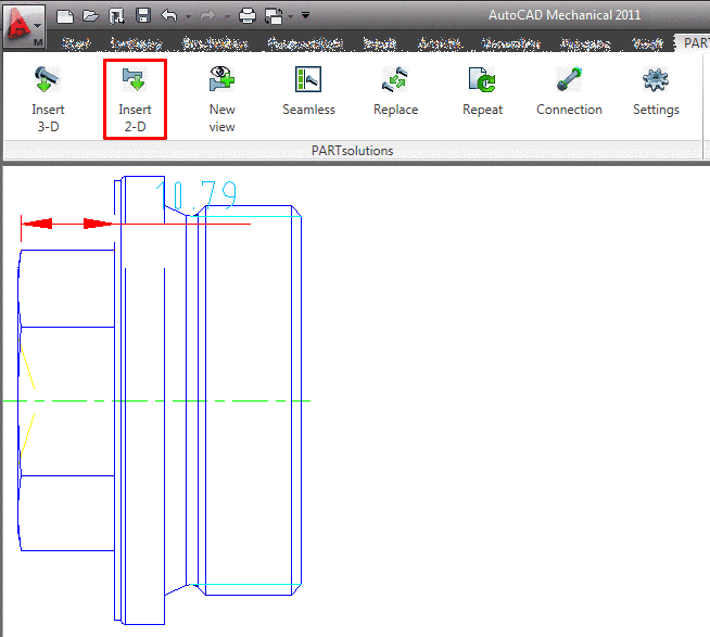
In order to export special derivations to the CAD system, proceed as follows:
Call up PARTdataManager in the CAD system via the PARTsolutions menu -> Insert 2D.
-
After selection of the desired part click on
Export to CAD.Note On this please regard the setting options under Section 3.3.9, “"Export to CAD" tabbed page ”.
-
Select the special desired view here.
-> The special derivation or view is transferred to the CAD system.
[75] For PARTcommunity as well
[76] The possible scales are defined administratively in the configuration file. See Section 1.1.6.7.1, “ 2dscales.cfg - Use scale for 2D view ” in PARTsolutions / PARTcommunity4Enterprise - Administration Manual.
[77] Default values for the paper formats are given per configuration file. See under Section 5.4.4, “ 2D derivation: create own views ” in eCATALOGsolutions Manual.
[78] ISO 8826-1 says, that the general, simplified depiction of bearings has to be performed with hatches in the same direction for all components with the same position number (rolling elements excluded).
