Manual
Login
Our 3D CAD supplier models have been moved to 3Dfindit.com, the new visual search engine for 3D CAD, CAE & BIM models.
You can log in there with your existing account of this site.
The content remains free of charge.

Top Links
Manual
 |
![[Note]](/community/externals/manuals/%24%7Bb2b:MANUALPATH/images/note.png) |
Note |
|---|---|
|
The functions of the toolbar in the 3D window are described under Section 3.1.1.7.5, “ "3D preview" window ”. In the following the special functions of the Part comparison are described. | |
-
-
The functions for automatic alignment are found in the 3D comparison section top left in the toolbar:
Overlay components : Possibly the functions Original rotation and centered position and Original rotation and position more effective.
Automatically calculate aligned rotation and position: Is according to the context menu command Center parts.
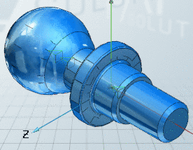
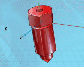
Original rotation and centered position (best fit)
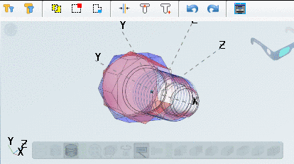
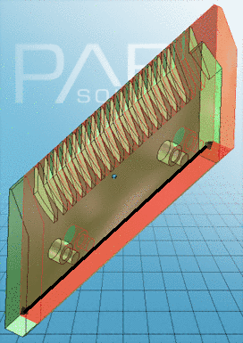
In the side view you can see, that the parts are not 100% identic.
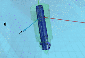
In the section view you can optimally see the differences. See Section 3.1.1.6.10.3.1.1, “Part comparison in sectional plane ”.
-
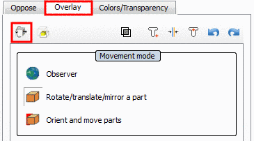
The button corresponds to the functions of orientation of parts or takes effect if parts have been manually moved or rotated. With Undo you can restore the last position.
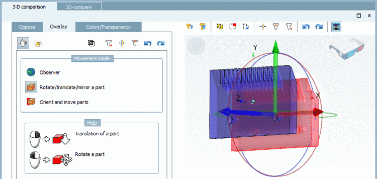
Expert mode: With click on the button at the left side a section with the Oppose, Overlay and Colors/Transparency index pages is displayed.
Detailed information on this is found under Section 3.1.1.6.10.3.2, “ Expert mode ”.
-
In the context menu of 3D comparison you can find the following menu items:
-
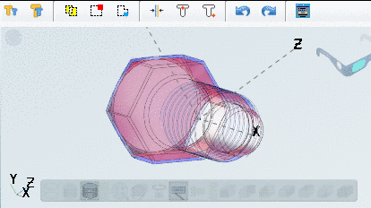
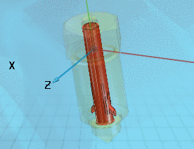
In the sectional plane the part differences are quite clear at a glance.
A detailed description of the functionality is found under Section 3.1.1.6.10.3.1.1, “Part comparison in sectional plane ”.
-
Measuring grid [56]


Select a sectional plane and the desired offset from zero plane.
Click on the
respective button in the toolbar  or alternatively on the command Define section cut... in the context menu of
the 3D window.
or alternatively on the command Define section cut... in the context menu of
the 3D window.

After calling the function a navigation cross with 6 arrows is displayed.
See Section 3.1.1.6.10.3.5, “ Colors/Transparency tabbed page ”.
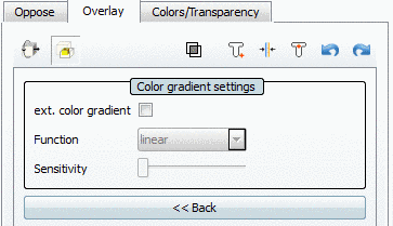
In the Expert mode  the dialog sections (already known from earlier
versions) with the Oppose, Overlay and Colors/Transparency index pages are
shown.
the dialog sections (already known from earlier
versions) with the Oppose, Overlay and Colors/Transparency index pages are
shown.
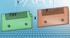
The basis for comparison are the parts, loaded as 1st and 2nd project.
-
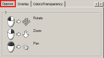
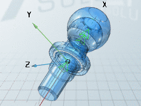
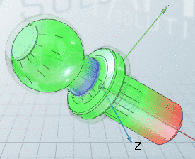
The parts to be compared are arranged along the X-axis.
You can rotate, zoom, and move the 3D view as a whole.
In this mode there are no other functions available. Therefore, switch to the Overlay index page.
-
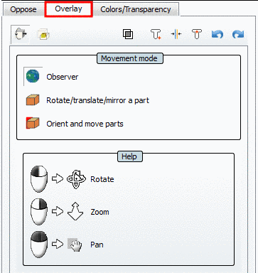
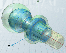
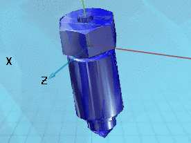
The parts to be compared are displayed overlaid.
In the Observer mode (default) you can rotate, zoom, and move the 3D view as a whole.
The following buttons are shown on the Overlay index page.
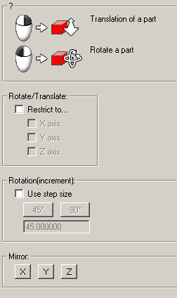
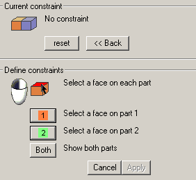
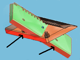
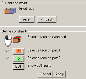
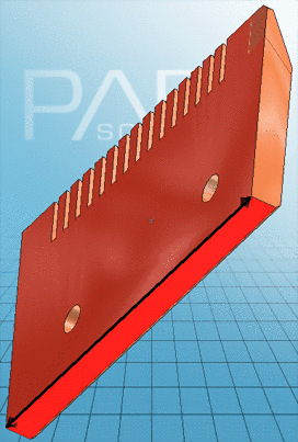
Rotate/Move/Mirror -> Movement mode...
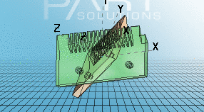
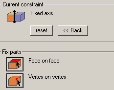
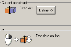
In the transaction mode you can move the parts as a whole or separated.
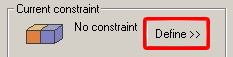
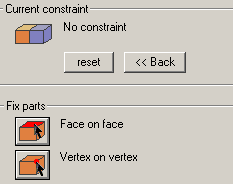
Furthermore the parts to compare can be fixed via angles or planes. Thus directed movement can be performed (e.g., movement along an axis).
A detailed description is found under Section 3.1.1.6.10.3.3, “ Movement and orientation”.
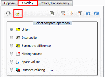
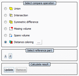
Compare geometrically -> Select compare operation
In this mode you can choose different comparison operations and thus clarify the differences between the parts to be compared.
A detailed description on this is found under Section 3.1.1.6.10.3.4, “ Comparison operations”.


|
Overlay -> Compare geometrically
|
|
|
|
|
|
|
|
|
|
|
|
|
|
|
|
|
|
|
|
|
|
|
|
|
|
|
[a] The exemplifying objects are "valve DIN 2814-B" and "bolt DIN 2814-D". | ||


The Transparency settings are used in the 3D view.
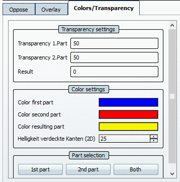
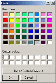
The Color settings are used all-around.
The setting is used in the 2D comparison.
In order to prevent "Hidden edges" from disturbing the depiction, the brightness of these has been set to 25% by default. Via setting option Hidden edges brightness (2D) you can adjust the brightness, if needed.


