Manual
Login
Our 3D CAD supplier models have been moved to 3Dfindit.com, the new visual search engine for 3D CAD, CAE & BIM models.
You can log in there with your existing account of this site.
The content remains free of charge.

Top Links
Manual
 |
Using an example, the following shows how you can create a configuration in the PARTdataManager step by step and individually.
|
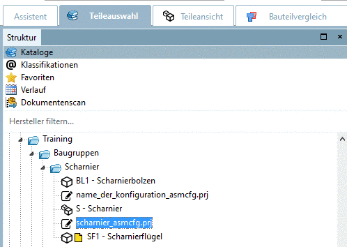
In the PARTdataManager Part selection select a configuration.
|
|
||||
|
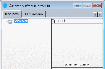
Afterwards, in the Assembly dialog area in the Tree view only the Description will be displayed while the Option list remains empty. |
|

|
Now one or more configuration elements will be displayed in the selection list. The configuration elements are already applied yet they must first be selected and activated. |
|

--> The start element is shown in the Tree view as subdirectory of the project (in this case "hinge").
![[Note]](/community/externals/manuals/%24%7Bb2b:MANUALPATH/images/note.png) |
Note |
|---|---|
The display first shows up in red writing , since the start element has not yet been further specified (see the following figure.) | |
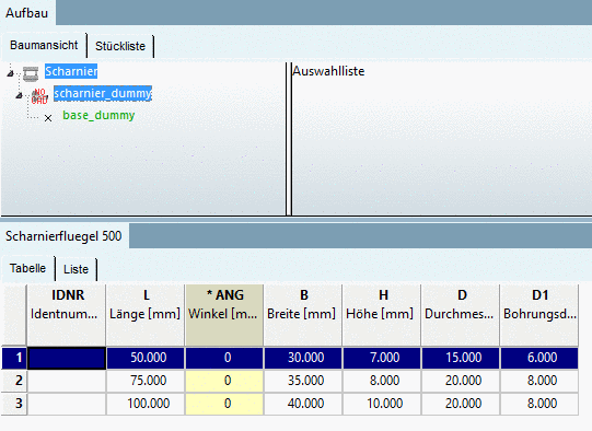
Select a characteristic for the start element (click on row number in table).
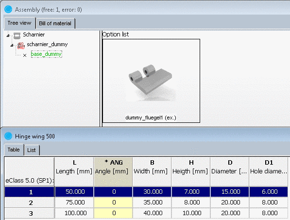
-->The start element is inserted, the corresponding 3D and/or 2D view shows up. (If a dummy start part was used this will not yet occur, but the next element.)
In the Tree view below the parts - as long as there are other connection parts - you can see the option Connection points . In the 3D view, these are displayed as small green pyramid symbols (see Fig. „ Connection points in tree view and 3D view “).
You can add assembly sections to each connection point from the Option list.
The insertion points in the Tree view are color coded:
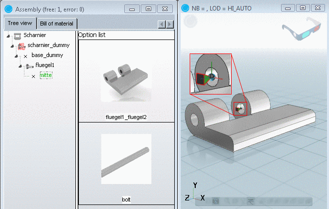
If you want to know where a specific connection point is located, mark its name in the Assembly in the Tree view. --> In the 3D view the respective pyramid symbol gets a red border.
You can insert individual elements in the way just described until all suggestions have been installed. Then you only have branching in black writing.
|
Note |
|---|---|
If there are several table rows per part, you can change the specification. The display is automatically adjusted in the 3D preview . | |
The following figure shows the completely assembled configuration:

